Before diving into the technical details, the TDA2009 pinout becomes essential to understand how its dual-channel architecture is implemented internally. The IC is widely used as a compact stereo amplifier solution, providing strong output performance with high stability and low distortion. Its robust design makes it suitable for home audio, automotive systems, and various medium-power sound applications.
Introduction
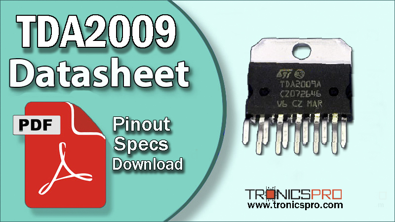
The TDA2009 is a dedicated stereo audio power amplifier IC designed for medium-power audio systems. It consists of two high-quality amplifier stages built into one package, making it ideal for stereo speaker setups. Its excellent noise rejection, thermal capability, and internal protection circuits allow it to maintain clear audio output even under demanding conditions.
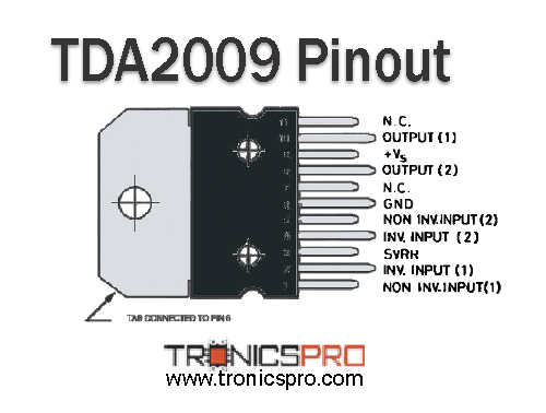
Pin Configuration / Pinout of TDA2009 Power Amplifier IC

Understanding the TDA2009 Pinout Configuration
The TDA2009 features 11 pins, arranged to support two separate input and output channels. Each amplifier section has its own non-inverting input, inverting input, and output pins. In addition, the IC includes a shared ground and a single supply voltage pin. This configuration simplifies stereo circuit design, reduces component count, and enables efficient board layouts.
| Pin# | Pin Name |
|---|---|
| 1 | NON-INV-INPUT 1 |
| 2 | INV-INPUT 1 |
| 3 | SVRR |
| 4 | INV-INPUT 2 |
| 5 | NON-INV-INPUT 2 |
| 6 | GND |
| 7 | NC |
| 8 | OUTPUT 2 |
| 9 | +Vs |
| 10 | OUTPUT 1 |
| 11 | NC |
Note: DATASHEET DOWNLOAD button is provided end of this article.
TDA2009 Key Features
- Dual-channel stereo audio amplification
- Low harmonic and crossover distortion
- High output stability
- Short-circuit protection
- Thermal shutdown protection
- Strong noise immunity
- Minimal external components required
TDA2009 Specifications/Characteristics
- Supply voltage (Vs): 28V
- Total power dissipation (Ptot): 20W
- Storage temperature range (Tstg): −40°C to 150°C
Key Applications of TDA2009 Power Amplifier IC
- Stereo audio amplifier modules
- Home speaker systems
- Car audio systems
- Multimedia audio units
- DIY stereo amplifier projects
TDA2009 Equivalent ICs / Alternatives
(Verify pin compatibility before using substitutions)
- TDA1517 (car stereo amplifier IC)
- TDA2005 (bridge amplifier)
- TDA2004
- TDA2030 (lower power alternative)
- LM1875 (higher-quality audio amplifier alternative)
More Circuit Layouts


Working Principle of TDA2009
The TDA2009 operates as a dual Class-AB audio amplifier, where each channel amplifies the input audio signal independently. The IC internally balances biasing to minimize crossover distortion, ensuring smooth and linear output. By using differential inputs and optimized feedback paths, it maintains high fidelity while preventing noise buildup. Integrated protection circuits safeguard against overload, overheating, and output shorts.
Frequently Asked Questions (FAQ)
Q1: What is the typical output power of the TDA2009?
The TDA2009 provides sufficient output for medium-power stereo applications, depending on speaker impedance and supply voltage.
Q2: Can the TDA2009 be used in automotive systems?
Yes, it is widely used in car audio systems due to its reliability and low distortion performance.
Q3: Does the TDA2009 require a heat sink?
Yes, proper heat sinking is necessary to maintain thermal stability and prevent overheating.
Q4: What speaker impedance is recommended?
The IC works well with commonly used 4Ω–8Ω speakers.
Conclusion
The TDA2009 stereo amplifier IC is a reliable and efficient solution for medium-power audio systems. Its dual-channel architecture, strong thermal characteristics, and built-in protection features make it a highly dependable choice for both DIY enthusiasts and commercial audio designers. With its stable performance and clean output, the TDA2009 remains a popular option for stereo sound applications.
Datasheet of TDA2009 Power Amplifier IC
Click the following Button below to download the datasheet of TDA2009 :
More projects, You may like:
- Video Transmitter DIY Homemade FM Radio Transmitter
- Adjustable Power Supply DIY Battery Charger
- 12V-220V 500 Watt inverter DIY Homemade
- MPPT Solar Charge Controller DIY Homemade
- DIY LA4440 bass amplifier homemade
For more project and circuit diagrams, you can go through the Schematics in the main menu where you can find many interesting projects and circuit diagrams like audio amplifier circuits, voltage booster circuit, battery charger circuit and timer circuits etc., which are all beginner circuit projects. Feel free to check them out!
Thank you for visiting the article.
You may also like:
![TL074 Op-Amp IC Datasheet]()
TL074 Op-Amp IC Pinout Datasheet
![tda2008 datasheet pinout equivalent specification application]()
TDA2008 Pinout, Equivalent, Application, Datasheet
![tda2004 datasheet pinout equivalent specification application]()
TDA2004 Pinout, Equivalent, Application, Datasheet
![tda7297 datasheet pinout equivalent specification application]()
TDA7297 Pinout, Equivalent, Application, Datasheet
![LM7909 datasheet pinout equivalent specification application]()
LM7909 Pinout, Equivalent, Application, Datasheet
![NE555 Timer IC Pinout Datasheet]()
NE555 Timer IC Pinout Datasheet
![tda2003 datasheet pinout equivalent specification application]()
TDA2003 Pinout, Equivalent, Application, Datasheet
![tda7454 datasheet pinout equivalent specification application]()
TDA7454 Pinout, Equivalent, Application, Datasheet