Introduction
In the world of audio amplification, achieving powerful and distortion-free bass reproduction is a pursuit cherished by audiophiles and music enthusiasts alike. A Subwoofer serves as a specialized loudspeaker engineered to reproduce audio signals characterized by lower frequencies. Its primary role revolves around enhancing the quality of bass in audio signals. One integral component that makes this possible is the Subwoofer Amplifier Circuit 100W. This circuit, boasting 100W of power, coupled with the LM7332 operational amplifier, is a gateway to an audio world where deep, resonating bass tones come to life. In this article, we will explore the details of this circuit, exploring its specifications, the remarkable LM7332 IC, and how it all comes together to elevate your audio experience.
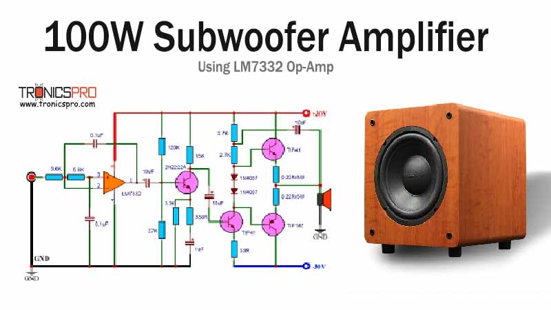
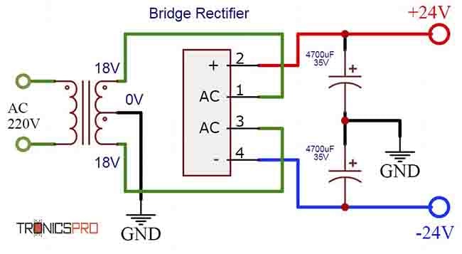
The following subwoofer amplifier circuit 100w system capable of generating sound signals within the frequency range of 20 Hz to 200 Hz, boasting an impressive power output of 100W, ideal for driving a 4-ohm speaker with a +/-30v power supply.
Subwoofer Amplifier Circuit 100W
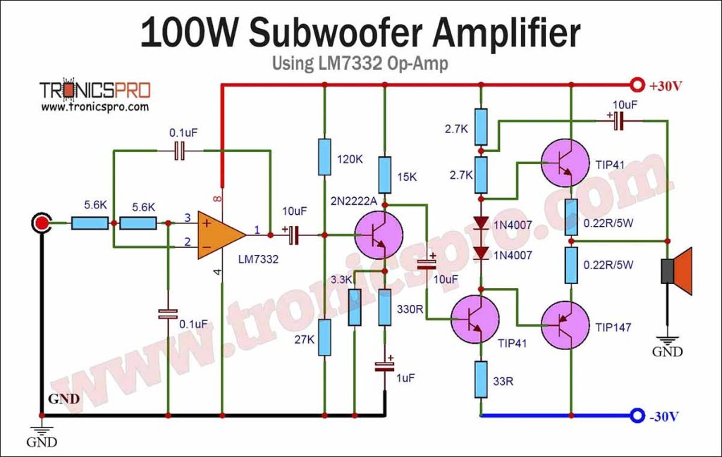
This project can be built using a few basic cheap components. The circuit diagram of this subwoofer amplifier is shown below.
More Circuit Layouts


Components List of Subwoofer Amplifier Circuit 100W
Following is the list of all components used in the above subwoofer amplifier circuit diagram of 100w:
- TIP147, PNP Transistor x 1
- TIP41 Transistor x 2
- 2N222A Transistor x 1
- OPAMP LM7332 IC x 1
- 5.6K Resister x 2
- 120K Resister x 1
- 27K Resister x 1
- 15K Resister x 1
- 3.3K Resister x 1
- 330 Ohms Resister x 1
- 33 Ohms Resister x 1
- 2.7 K Resister x 2
- 0.22 ohm/5w Resister x 2
- 0.1uF Capacitor x 2
- 10uF Capacitor x 3
- 1uF Capacitor x 1
- 1N4007 Diode x 2
- Dual Power Supply +/-30V
- Speaker 4 Ohms
Specifications of the LM7332 Operational Amplifier IC:
Before we dive into the circuit itself, let’s understand the capabilities of the LM7332 IC, as it plays a pivotal role in shaping the amplifier’s performance. The LM7332 is a dual operational amplifier IC designed to deliver high precision and low distortion amplification. Here are some key specifications:
High Gain-Bandwidth Product: The LM7332 boasts a high gain-bandwidth product, typically in the range of hundreds of megahertz, ensuring accurate amplification of audio signals across a wide frequency spectrum.
Low Input Offset Voltage: With a low input offset voltage, often in the millivolt range, this IC minimizes errors and distortion in the amplified audio signal.
Low Noise: The LM7332 is engineered to keep noise levels to a minimum, ensuring that your audio remains clean and clear even at high amplification levels.
Dual Amplification: It features two independent operational amplifiers in a single package, making it ideal for applications like the subwoofer amplifier circuit.
Wide Supply Voltage Range: The LM7332 can operate on a wide supply voltage range, accommodating various power supply configurations.
Working Explanation of Subwoofer Amplifier Circuit 100W
The audio signal undergoes meticulous filtering through a low-pass filter, a process executed by the operational amplifier (OPAMP). This filter selectively permits frequencies below and up to 200Hz to pass through while effectively blocking higher frequencies. The resulting low-frequency signal is then channeled into the input of the audio transistor TIP41, facilitated by the coupling capacitor (10uF). TIP41 operates in class A mode, amplifying the input signal significantly at its output. This amplified signal is subsequently transformed into a high-impedance signal by the output transistor TIP41, and it is presented to the class AB power amplifier. The two Darlington output transistors collaboratively handle the positive and negative halves of the signal, collectively forming a complete output cycle. The inclusion of 0.22-ohm emitter resistors minimizes differences between the matching transistors, while diodes are employed to ensure minimal overlap distortion. This high-powered output signal is then utilized to drive a low-impedance loudspeaker or subwoofer, typically around 4 Ohms.
Conclusion:
The Subwoofer Amplifier Circuit Diagram with its 100W output power, stands as a testament to this pursuit. When coupled with the LM7332 operational amplifier IC, it becomes a force to be reckoned with, delivering precision, clarity, and depth to your audio experience.
As we explored the specifications of the LM7332 IC, we discovered its role in ensuring low distortion, high precision, and minimal noise in the subwoofer amplifier circuit. Together, they create an audio synergy that elevates your music or movie-watching experience to new heights. So, whether you’re a bass enthusiast or simply seeking an immersive audio experience, the Subwoofer Amplifier Circuit 100w with the LM7332 IC is a remarkable choice that promises to fill your space with rich, resonant bass frequencies, bringing your audio to life.
More projects, You may like:
- Video Transmitter DIY Homemade FM Radio Transmitter
- Adjustable Power Supply DIY Battery Charger
- 12V-220V 500 Watt inverter DIY Homemade
- 12V-220V H-Bridge Inverter DIY Homemade
- MPPT Solar Charge Controller DIY Homemade
- 18650 battery bank free charge protection module
- D718 B688 Bass Amplifier Homemade DIY
- C5200 Bass Amplifier DIY Homemade with Volume
- DIY LA4440 bass amplifier homemade
- C5200 A1943 TDA2030 Amplifier DIY Homemade
For more project and circuit diagrams, you can go through the Schematics in the main menu where you can find many interesting projects and circuit diagrams like audio amplifier circuits, voltage booster circuit, battery charger circuit and timer circuits etc., which are all beginner circuit projects. Feel free to check them out!


Thank you for visiting the article.


Superb article thank you for sharing.
Thanks for visiting site & comments.
I think there is mistake tip147 complimentary transistor is tip142
Greetings from India boss! This ckt appears very interesting and I’m inclined to make it, however I have some inhibitions about the total success of this ckt. I must be missing something here or there must be some ommission on your part regarding the missing bias resistor on the input transistor Tip41 of the Pwr stage. If I’m not mistaken, it should be connected through approx 22-27k resistor from the speaker end which will include some negative fb as well. It can also be taken from the positive line as well, I suppose.