Introduction
Circuit Diagram of Non-Inverting AC Power Amplifier using MC1538R and MC1556G ICs
An amplifier is a circuit that amplifies or increases the amplitude of the input signal, thereby increasing the output signal’s power. Amplifiers are widely used in audio systems, instrumentation, and communication devices, among other applications. An AC amplifier or AC power amplifier amplifies the AC input signal’s power, allowing it to drive a load with a higher power. In this article, we will discuss the circuit diagram of a non-inverting AC power amplifier using MC1538R and MC1556G ICs.
MC1538R and MC1556G ICs
MC1538R and MC1556G are dual-operational amplifiers designed for use in analog and digital circuits. They are low-cost, general-purpose devices that can be used in various applications, including amplifiers, oscillators, and active filters. These ICs are characterized by high input impedance, low output impedance, and high gain-bandwidth products. They can also operate in a wide range of supply voltages, making them suitable for battery-powered applications.
Circuit Diagram
of Non-Inverting AC Power
The input signal is applied to the non-inverting input terminal of the operational amplifier (OP-AMP) MC1538R. The feedback resistor (RF) is connected between the output terminal of the OP-AMP and the inverting input terminal. The resistor (R1) and capacitor (C1) are connected in parallel between the inverting input terminal and ground to set the input impedance and frequency response of the amplifier.

More Circuit Layouts


A non-inverting AC power amplifier amplifies the input signal without inverting its phase. The basic circuit diagram of a non-inverting AC power amplifier using MC1538R and MC1556G ICs is shown below.
Working Explanation
of Non-Inverting AC Power
The output of the first OP-AMP (MC1538R) is fed to the input of the second OP-AMP (MC1556G). The feedback resistor (RF1) and load resistor (RL) are connected between the output terminal of the second OP-AMP and the inverting input terminal to set the gain and output impedance of the amplifier.
The gain of the non-inverting AC power amplifier is given by the following equation:
Gain = (1 + RF/R1) * (RF1/RL)
The amplitude of the output signal is determined by the gain of the amplifier and the amplitude of the input signal.
Applications
The non-inverting AC power amplifier using MC1538R and MC1556G ICs can be used in various applications, including audio amplifiers, power supplies, and instrumentation circuits. They are suitable for driving speakers, motors, and other high-power loads.
Conclusion
In conclusion, the non-inverting AC power amplifier using MC1538R and MC1556G ICs is an essential circuit for amplifying AC input signals with high power. This circuit provides high gain, low output impedance, and high input impedance, making it suitable for various applications. It is an ideal circuit for audio systems, instrumentation, and communication devices, among other applications.
More projects, You may like:
- Video Transmitter DIY Homemade FM Radio Transmitter
- Adjustable Power Supply DIY Battery Charger
- 12V-220V 500 Watt inverter DIY Homemade
- 12V-220V H-Bridge Inverter DIY Homemade
- MPPT Solar Charge Controller DIY Homemade
- 18650 battery bank free charge protection module
- D718 B688 Bass Amplifier Homemade DIY
- C5200 Bass Amplifier DIY Homemade with Volume
- DIY LA4440 bass amplifier homemade
- C5200 A1943 TDA2030 Amplifier DIY Homemade

You may also like:
![STK4141 Stereo Amplifier Circuit Diagram 50W]()
STK4141 Stereo Amplifier Circuit Diagram
![Op-Amp With Hysteresis Circuit Diagram]()
Op-Amp With Hysteresis Circuit Diagram
![Headphone Amplifier Circuit Diagram using NE5532 IC]()
Stereo Headphone Amplifier Circuit Diagram using NE5532
![1000W Power Amplifier Circuit using 2SC5200 & 2SA1943]()
1000W Power Amplifier Circuit Diagram using 2SC5200 & 2SA1943
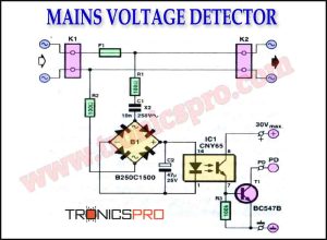
![Mains Voltage Detector Circuit Diagram]()
Mains Voltage Detector Circuit Diagram
![TDA2030 Amplifier Single Supply Circuit Diagram]()
TDA2030 Amplifier Single Supply Circuit Diagram
![100W HiFi Amplifier Circuit using 2SC3280 Transistors]()
100W HiFi Amplifier Circuit Diagram using 2SC3280 Transistors
![Auto Power Off Circuit Diagram]()
Auto Power off Circuit Diagram