Introduction
A power amplifier is an essential component in any audio system, as it amplifies the weak audio signals to a level that can drive speakers and produce audible sound. In this article, we will discuss a 100W power amplifier circuit diagram that uses MOSFET IRFP244 and IRFP9240 in the output section, MJE340 and MJE350 in the driver section, and MPSA43 in the preamplifier section. This circuit design is capable of delivering high-quality audio with sufficient power to drive speakers effectively.
Specification of Transistors:
- IRFP244:
The IRFP244 is a power MOSFET transistor with a maximum drain current of 55A and a drain-source voltage rating of 250V. It features low on-resistance and high switching speed, making it an ideal choice for high power amplifier applications. - IRFP9240:
The IRFP9240 is also a power MOSFET transistor, but it has a higher drain current rating of 12A and a drain-source voltage rating of 200V. This transistor exhibits low on-resistance and excellent gate charge characteristics, making it suitable for power amplifier circuits. - MJE340:
The MJE340 transistor is a NPN bipolar junction transistor (BJT) with a collector current rating of 0.5A and a collector-emitter voltage rating of 300V. It offers good linearity and can provide sufficient current gain in the driver section of the amplifier circuit. - MJE350:
The MJE350 is a PNP BJT transistor, complementing the MJE340. It also has a collector current rating of 0.5A and a collector-emitter voltage rating of 300V. The MJE350 exhibits similar characteristics to the MJE340 and can effectively drive the MOSFETs in the amplifier circuit. - MPSA43:
The MPSA43 is a small signal NPN BJT transistor with a collector current rating of 0.5A and a collector-emitter voltage rating of 200V. It is commonly used in low-power amplifiers and preamplifier stages due to its good high-frequency performance and low noise characteristics.
Amplifier Circuit Diagram using MOSFET
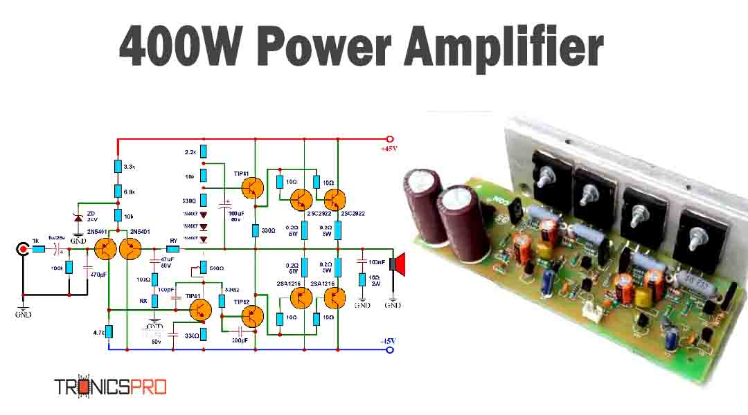
This project can be built using a few basic components. The circuit diagram of this project is shown below.
Caution: Website contains information on high voltage circuits. Proceed at your own risk, ensuring proper knowledge and precautionary measures to prevent electric shock or injury.
More Circuit Layouts








Components List of Amplifier Circuit Diagram using MOSFET
Following is the list of all components used in this project:
Transistors:
- IRFP244 Transistor x 1
- IRF9240 Transistor x
- MJE350 Transistor x
- MJE340 Transistor x
- BC546 Transistor x 2
- MPSA43 Transistor x 3
Resisters:
- 39Ω Resistor x 1
- 390Ω Resistor x 1
- 1k Resistor x 1
- 1.5k Resistor x 1
- 4.7k Resistor x 1
- 15k Resister x 1
- 22k Resister x 1
- 33k Resister x 1
- 47k Resister x 1
- 150k Resister x 1
- 330Ω Resister x 3
- 10Ω/2W Resister x 1
- 0.33Ω/5W Resister x 2
- 0.22Ω/10W Resister x 1
Capacitors:
- 100nF/100V Capacitor x 2
- 47uF/100V Capacitor x 1
- 470pF/100V Capacitor x 1
- 470nF/63V Capacitor x 1
- 10pF/100V Capacitor x 1
Miscellaneous:
- 1n4002 Diode x 1
- 4Ω 100W Speaker
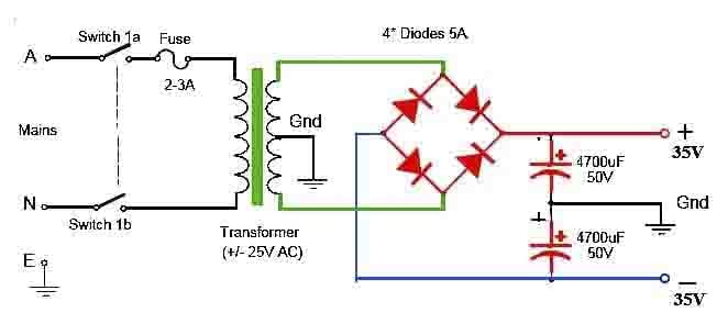
- ±35-40V Dual Power Supply
Explanation of Amplifier Circuit Diagram using MOSFET
The 100W power amplifier circuit diagram employs a complementary push-pull configuration using MOSFET IRFP244 and IRFP9240 in the output stage. The preamplifier section consists of an MPSA43 transistor, which amplifies the weak input audio signals. The driver section comprises MJE340 and MJE350 transistors, which provide sufficient current drive to the MOSFETs.
The circuit operates on a dual supply voltage of ±35V, which provides the necessary power to drive the MOSFETs in the output stage. The MPSA43 preamplifier transistor amplifies the input signals and feeds them to the driver section, composed of MJE340 and MJE350 transistors. These transistors provide the required current gain to drive the power MOSFETs effectively.
The output stage consists of IRFP244 and IRFP9240 MOSFETs, which handle the heavy load current and deliver the amplified audio signals to the speakers. These MOSFETs offer low on-resistance, ensuring minimum power losses and high efficiency.
Conclusion
The 100W power amplifier circuit diagram discussed in this article showcases the usage of MOSFET IRFP244 and IRFP9240, along with MJE340, MJE350, and MPSA43 transistors in various sections. This circuit design allows for the amplification of weak audio signals to drive speakers effectively. The specifications of each transistor ensure the proper functioning of the amplifier circuit, providing high-quality audio output. With careful construction and proper component selection, this amplifier circuit can deliver powerful and clear sound reproduction.
More projects, You may like:
- Video Transmitter DIY Homemade FM Radio Transmitter
- Adjustable Power Supply DIY Battery Charger
- 12V-220V 500 Watt inverter DIY Homemade
- MPPT Solar Charge Controller DIY Homemade
- DIY LA4440 bass amplifier homemade
For more project and circuit diagrams, you can go through the Schematics in the main menu where you can find many interesting projects and circuit diagrams like audio amplifier circuits, voltage booster circuit, battery charger circuit and timer circuits etc., which are all beginner circuit projects. Feel free to check them out!

Thank you for visiting the article.


