
This article will discuss a 200W amplifier circuit that utilizes a couple of pairs of 2SD1047 and 2SB817 transistors in the output section, TIP41 and TIP42 transistors in the driver section, and A1015 transistors in the preamplifier section.


This article will discuss a 200W amplifier circuit that utilizes a couple of pairs of 2SD1047 and 2SB817 transistors in the output section, TIP41 and TIP42 transistors in the driver section, and A1015 transistors in the preamplifier section.

The amplifier circuit that has gained popularity in recent times is the 100W Amplifier Circuit Diagram using TIP142 and TIP147 transistors. This circuit holds immense potential for audio enthusiasts and DIY hobbyists looking to build their own amplifier.

In this article, we will delve into the details of 100W Amplifier Circuit diagram, which utilizes dual 2SC5200 transistors in the output section, TIP41 & TIP42 transistors in the driver section, and 2SA1015 transistors in the preamplifier section alongwith its working principle, and specifications of the transistors used.
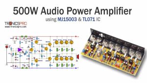
In this article, we will explore a 500W amplifier circuit diagram that utilizes the MJ15003 transistor and TL071 IC. This circuit diagram presents a powerful, high-performance amplifier design suitable for various applications.

A 500W amplifier circuit using 2SC2922 & 2SA1216 high-quality transistors can provide both power and fidelity for an exceptional audio experience. This article will explore the circuit diagram of such an amplifier, utilizing 2SC2922 & 2SA1216 Sanken transistorsand C2168, A958, D438 & B560 transistors in the driver and preamplifier sections.

Stereo Tone Control Circuit Diagram using NE5532 IC is a versatile and efficient audio circuit that can enhance the audio quality of any stereo system. This circuit utilizes the NE5532 IC, a high-performance operational amplifier, to deliver excellent audio performance across a wide range of frequencies.

Amplifiers play a crucial role in boosting the power of a signal. One such amplifier is the 100W Amplifier Circuit, which can deliver a significant power output while maintaining excellent fidelity. This article will explore the circuit diagram of a 100W Amplifier Circuit that utilizes dual TIP36 transistors in the output section, BD139, BD140 & MPSA92 transistors in the driver and preamplifier sections.

This article explores the construction of an OCL Amplifier Circuit Diaram using TIP31-TIP32, with a focus on the dynamic quartet of transistors: TIP31, TIP32, C1815, and A1015.

In this article, we will explore three input Microphone Preamplifier Circuit Diagram using LM348 single IC. The LM348 is a versatile operational amplifier (Op-Amp) that provides a high-quality, low-noise amplification solution for various audio application

Step by step guide of 200W MOSFET Amplifier Circuit. This circuit utilizes two pairs of ECX10N16 and ECX10P16 MOSFETs in the output section, two pairs of MJE340 and MJE350 transistors in the driver section, and two pairs of BC556 transistors in the preamplifier section. Additionally, an overload protection circuit is incorporated, featuring two BC556 transistors.

 Variable Power Supply 0-30V_10A Circuit Diagram
 C5200 A1943 TDA2030 Amplifier DIY Homemade
 DIY LA4440 bass amplifier homemade
 Bass Tone Control Circuit Diagram – TRONICSpro
 2N3055 stereo amplifier homemade bluetooth diy
 500W Power Amplifier Circuit using c5200 a1943
 DIY bass treble volume homemade Tone Control
 Subwoofer Amplifier Circuit Diagram using TDA2030
 KSP92 Pinout, Equivalent Application Datasheet
 KSP44 Pinout, Equivalent Application Datasheet
 MPSA92 Pinout, Equivalent Application Datasheet
 MPSA42 Pinout, Equivalent Application Datasheet
 PN200 Pinout, Equivalent Application Datasheet
 PN100 Pinout, Equivalent Application Datasheet
 MJE802 Pinout, Equivalent Application Datasheet
 MJE800 Pinout, Equivalent Application Datasheet