Introduction
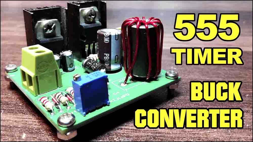
The 555 timer integrated circuit is a versatile tool in electronics. It was introduced by Signetics Corporation in 1971 and has gained popularity as a stable, cost-effective, and easily accessible device. It can be used to build simple electronic circuits such as a buck converter, which is a DC to DC power converter. In this article, we are going to show the steps involved in how to make buck converter using 555 timer integrated circuit.

Circuit Diagram of How to Make Buck Converter
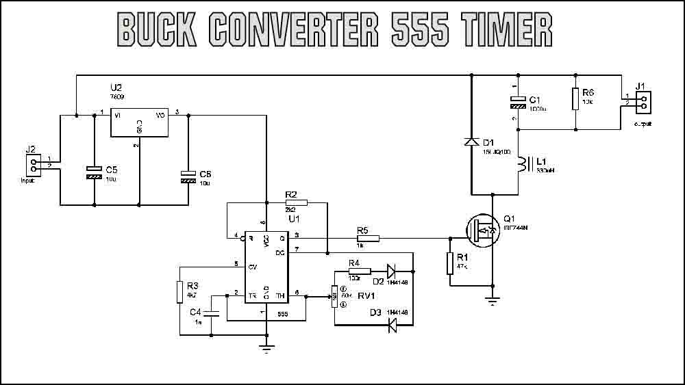
This project can be designed using a few basic components. The circuit diagram of this project is shown below.
More Circuit Layouts


Components List of How to Make Buck Converter
Following is the list of all components used in this project:
- 1X 555 Timer IC
- 1X IRFZ44 MOSFET
- 1X SB340 Diode
- 1X 1N4148 Diode
- 1X 10K Tripot
- 1X 100 OHM Resistors
- 1X 1K Resistor
- 1X 2.2K Resistor
- 1X 10K Resistors
- 1X 47K Resistor
- 1X 1nF Capacitor
- 1X 220uF Capacitor
- 2X 2PIN Terminal Block
- Jumper Wires
Conclusion
Making a buck converter using a 555 timer IC is an efficient and cost-effective solution to DC to DC voltage conversion. The steps involved in creating a this project are relatively simple and can be accomplished by following the guidelines mentioned in this article. By building a this device, you can save on power consumption and improve the performance of your electronic devices. So, if you are looking for a reliable way to enhance your electronic devices, consider building a buck converter using a 555 timer IC.
More projects, You may like:
- Video Transmitter DIY Homemade FM Radio Transmitter
- Adjustable Power Supply DIY Battery Charger
- 12V-220V 500 Watt inverter DIY Homemade
- 12V-220V H-Bridge Inverter DIY Homemade
- MPPT Solar Charge Controller DIY Homemade
- 18650 battery bank free charge protection module
- D718 B688 Bass Amplifier Homemade DIY
- C5200 Bass Amplifier DIY Homemade with Volume
- DIY LA4440 bass amplifier homemade
- C5200 A1943 TDA2030 Amplifier DIY Homemade


