Learn how to make your own a very simple diy homemade door alarm Alarm. It uses CPU battery holder/jacket with its cell, a 5 volts buzzer & 2 pieces of gem clips. This device is designed by me which is stand alone. This can be placed on doors or windows to alert someone, if they have been opened.

Basic components:
Take one piece of 5v buzzer which has two connections. And take one CPU battery compartment. It also has positive & negative connections. These two components are easily available from an old & obsolete CPU mother board.

More Circuit Layouts


Development images
used in DIY homemade door alarm
Joining components:
Stick both CPU battery compartment and 5 volts buzzer each other with supper glue as shown in the below image.

Turn the two negative pins of both components together and solder them. This way will provide negative voltage of the cell to buzzer directly.

Now take two gem clips/paper clips and straighten their legs as shown in the following image. These two pins will act as switch.

Soldering components:
Solder one pin to the positive pin of the battery compartment. Please insulate the pin properly to avoid short circuit with the negative connection beside it.

Also solder the other pin with the positive pin of the buzzer and insulate properly. Both the pins should not touch each other. Stick them properly with super glue. If you want to use pvc tape to wrap around the pins that will be much better.

After soldering both pins, it will look like the following image from the top

Now turn one of them upward with 90 degree angle. If you stick it with buzzer after turning upward, will be great.

Also turn the second pin upward with 90 degree after one inch distance.

Turn the same second pin (shown in above image) to left 90 degree and cut after half inch to reduce extra length.

Now turn the first pin forward 90 degree. This time the first pin after turning, should touch with the second pin. At this stage the buzzer will active with sound. You can put a small piece of paper in between the touch point of these two pins.

Turn the same first downward 90 degree.

Finally the device will look like the following image.

Cur the extra length of the first pin which is going downward. It must be little bit larger than the bottom surface of the device. So that when you fix it wilh the door, it should go upward a little bit and should disconnect the connection when the door is closed.

Testing the project:
Fix the device with the door as shown in the below image.

In the following image it shows that the door is closed. And the connection is disconnected. Because the pin is little bit larger than the bottom surface of the device. When the door will open, it will go downward with its tension. And this way it will be touched with the other pin and will alow buzzer to activate alarming.

I hope you will enjoy the project. Thanks for visiting the site and please don’t forget to share it with your friends. Thank you.
You may also like:
![Make Voice Controlled Light Thumbnail]()
How To Make Voice Controlled Light
![How to Make DC-to-DC Boost Converter using UC3843]()
How to Make DC to DC Boost Converter using UC3843
![Hand Gesture Controlled Car Thumbnail]()
Hand Gesture Controlled Car Robot - TRONICSpro
![How to Make DIY Variable Power Supply]()
How to Make DIY Variable Power Supply
![Motion Tracking Mobile Mount Thumbnail]()
How To Make Motion Tracking Mobile Mount
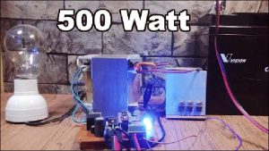
![12V-220V 500 Watt inverter DIY Homemade]()
12V-220V 500 Watt inverter DIY Homemade
![How To Make DIY Digital Soldering Station]()
How To Make DIY Digital Soldering Station
![How to Make Latching Relay]()
How to Make Latching Relay | Set Reset Relay