The BD544 pinout is an essential reference for using this high-power PNP transistor in amplifier and switching circuits. BD544 is designed for applications requiring high current and efficient power dissipation, such as audio amplifiers, voltage regulators, and power control stages. With a collector-emitter voltage of -40V and power dissipation of up to 70W, it delivers excellent linearity and reliability. Its complementary counterpart, the BD543 NPN transistor, shares identical voltage and current ratings, making them ideal for push-pull amplifier configurations.
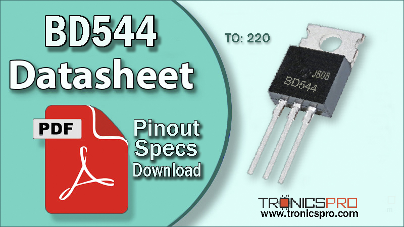
Introduction to BD544 PNP Transistor
The BD544 transistor is a silicon PNP power transistor developed for heavy-duty audio output and power regulation circuits. It can handle high collector currents while maintaining stability across a wide temperature range. Designed in a TO-220 metal package, BD544 offers superior thermal conductivity and mechanical durability, suitable for high-power setups that require robust heat dissipation.
In PNP configuration, BD544 conducts when its base is pulled low relative to the emitter. This characteristic makes it ideal for complementary amplifier stages when paired with its NPN partner BD543, enabling symmetric signal amplification with minimal distortion.
BD544 PNP Transistor
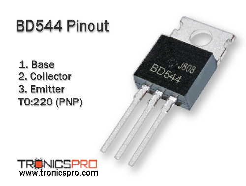
Pinout of BD544
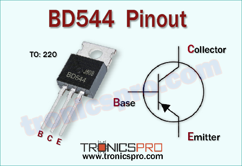
Understanding the BD544 Pinout Configuration
The BD544 pinout follows the standard TO-220 layout. Proper identification of each terminal is crucial to avoid misconnection, which could damage the transistor or circuit.
Pin Configuration of BD544 Pinout
| Pin# | Pin Name |
|---|---|
| 1 | Base |
| 2 | Collector |
| 3 | Emitter |
Key Features of BD544 Transistor
- PNP silicon transistor for high-current and power applications
- Excellent linearity and low harmonic distortion in audio circuits
- Durable TO-220 package for effective heat dissipation
- Suitable for complementary pairing with BD543 NPN transistor
- High thermal stability and reliability in continuous operation
- Compatible with standard amplifier circuit configurations
BD544 Transistor Datasheet and Specifications
- Collector-Emitter Voltage (Vce): -40 V
- Collector-Base Voltage (Vcb): -40 V
- Emitter-Base Voltage (Veb): -5 V
- Collector Current (Ic): -10 A
- Power Dissipation (Pc): 70 W
- DC Current Gain (hFE): 15 to 100
- Transition Frequency (fT): 3 MHz (typical)
- Package Type: TO-220
- Polarity Type: PNP
Working Principle of BD544 Transistor
The BD544 PNP transistor operates by controlling a large current between collector and emitter through a small current at the base terminal. When the base is driven negative relative to the emitter, the transistor allows current to flow from the emitter to collector.
This makes BD544 ideal for low-side control and amplifier output stages. When paired with BD543 (NPN), both form a complementary push-pull configuration, the BD543 handles the positive half of the waveform, while BD544 handles the negative half. This results in efficient amplification with reduced crossover distortion, a key factor in high-quality audio output stages.
More Circuit Layouts


Typical Applications of BD544
- High-power audio amplifier output stages
- Power switching and regulation circuits
- DC motor drivers and control units
- Industrial control systems
- Complementary push-pull amplifier configurations
NPN Complementary Transistor
The BD543 NPN transistor is the complementary pair to BD544. Both transistors share the same maximum ratings and are frequently used together in push-pull and class-AB amplifier circuits to achieve full waveform amplification with excellent efficiency and minimal distortion.
Equivalent Transistors and Alternatives
The BD544 can be replaced with other PNP high-power transistors with similar ratings. Some close alternatives include:
- MJ15004
- TIP36C
- 2SB554
- BDW94C
- 2SA1302
Always confirm voltage and pin compatibility before substitution.
Comparison Summary: BD544 vs BD543
The BD544 is a PNP transistor, while the BD543 is its NPN counterpart. Both share equal voltage ratings (40V) and power dissipation capacity (70W). In operation, BD543 conducts during the positive cycle of the signal, whereas BD544 conducts during the negative cycle.
This complementary operation ensures full signal reproduction in class-AB amplifier stages, reducing crossover distortion and improving output efficiency. The matched characteristics of BD543 and BD544 make them a preferred combination in stereo amplifiers and regulated power supply designs.
Frequently Asked Questions (FAQ)
What is the BD544 transistor used for?
It’s used for high-power audio amplifiers, voltage regulators, and switching circuits.
What is the package type of BD544?
It is enclosed in a TO-220 package, providing excellent heat management.
What is the BD544 pin configuration?
The BD544 pinout (from left to right, flat side facing you) is: Pin 1 – Emitter, Pin 2 – Collector, Pin 3 – Base.
What is the complementary transistor for BD544?
The complementary transistor is BD543, an NPN power transistor with identical voltage and current specifications.
Can I replace BD544 with TIP36C?
Yes, TIP36C can serve as a substitute if voltage and pin alignment are compatible.
Conclusion
The BD544 transistor is a reliable PNP silicon power device with 40V voltage capacity and 70W dissipation, perfectly suited for high-current and high-power applications. It offers consistent performance, thermal stability, and excellent linearity in amplifier and power control circuits.
When paired with its complementary NPN transistor BD543, it creates a balanced, efficient push-pull pair for audio output and regulation systems, delivering superior sound quality and stable performance under load.
Datasheet & Pinout of BD544 NPN Transistor
Click the following Button to download the datasheet of BD544 Transistor :
More projects, You may like:
- Video Transmitter DIY Homemade FM Radio Transmitter
- Adjustable Power Supply DIY Battery Charger
- 12V-220V 500 Watt inverter DIY Homemade
- MPPT Solar Charge Controller DIY Homemade
- DIY LA4440 bass amplifier homemade
For more project and circuit diagrams, you can go through the Schematics in the main menu where you can find many interesting projects and circuit diagrams like audio amplifier circuits, voltage booster circuit, battery charger circuit and timer circuits etc., which are all beginner circuit projects. Feel free to check them out!
Thank you for visiting the article
You may also like:
![bd540 transistor datasheet]()
BD540 Pinout, Equivalent, Applications, Datasheet
![TIP47 NPN Transistor Datasheet Pinout]()
TIP47 NPN Transistor Pinout Datasheet
![2n6043 datasheet pinout]()
2N6043 Pinout, Equivalent, Application, Datasheet
![MJE15032 NPN Transistor Pinout Datasheet]()
MJE15032 NPN Power Transistor Datasheet
![MJ15004 datasheet pinout]()
MJ15004 Pinout Equivalent Applications, Datasheet
![bf869 datasheet pinout equivalent specification application transistor]()
BF869 Pinout, Equivalent, Application, Datasheet
![BD180 PNP Transistor Datasheet]()
BD180 PNP Transistor Pinout Datasheet
![2n5191 datasheet pinout equivalent specification]()
2N5191 Pinout, Equivalent, Application, Datasheet