

Introduction
In the symphony of audio electronics, the OCL (Output Capacitor-Less) Amplifier Circuit stands out as a powerhouse, delivering both power and precision. This article explores the construction of an OCL Amplifier Circuit Diaram using TIP31 & TIP32, with a focus on the dynamic quartet of transistors: TIP31, TIP32, C1815, and A1015. As we journey through the intricacies of this circuit, audiophiles and electronics enthusiasts will discover a realm of high-fidelity sound reproduction.
Before delving into the specifications and assembly intricacies, let’s acquaint ourselves with the vital components:
TIP31 Transistor:
Voltage Rating: 60V
Current Rating: 3A
Power Dissipation: 40W
Gain (hFE): 25-75
Package: TO-220
TIP32 Transistor:
Voltage Rating: 60V
Current Rating: 3A
Power Dissipation: 40W
Gain (hFE): 25-75
Package: TO-220
C1815 Transistor:
Voltage Rating: 50V
Current Rating: 0.1A
Power Dissipation: 0.4W
Gain (hFE): 70-700
Package: TO-92
A1015 Transistor:
Voltage Rating: 50V
Current Rating: 0.15A
Power Dissipation: 0.4W
Gain (hFE): 60-320
Package: TO-92
These transistors play unique roles in the driver, preamplifier, and output sections, collectively forming a robust OCL Amplifier Circuit.
OCL Amplifier Circuit Diaram using TIP31
This project can be built using a few basic components. The circuit diagram of this project is shown below.


More Circuit Layouts


Components List of OCL Amplifier Circuit Diaram using TIP31
Following is the list of all components used in this project:
- TIP31 Transistor x 1
- TIP32 Transistor x 1
- C1815 Transistor x 4
- A1015 Transistor x 2
- 1N4007 Diode x 2
- 10k Resister x 2
- 15k Resister x 1
- 2k Resister x 2
- 100/1W Resister x 1
- 220 Resister x 1
- 1.2 Resister x 1
- 6.8k Resister x 1
- 820 Resister x 1
- 0.55W Resister x 2
- 1uF Capacitor x 1
- 220uF Capacitor x 1
- 33pF Capacitor x 1
Explanation of OCL Amplifier Circuit Diaram using TIP31
The input signal is processed through the driver and preamplifier sections, featuring C1815 and A1015 transistors, respectively. The amplified signal then passes through the output section, where TIP31 and TIP32 transistors collaborate to deliver substantial power to connected speakers. The absence of an output capacitor in the design ensures minimal distortion and improved signal integrity.
Building the Amplifier:
For those eager to embark on this audio journey, assembling the OCL Amplifier Circuit involves careful execution:
Component Placement: Begin by placing and soldering the transistors (TIP31, TIP32, C1815, A1015), resistors, capacitors, and other components onto the PCB.
Driver and Preamplifier Setup: Focus on connecting the C1815 and A1015 transistors in their respective sections, ensuring proper biasing and signal amplification.
Output Section Integration: Connect the TIP31 and TIP32 transistors in the output section, paying attention to their orientation and heat dissipation.
Power Supply Connection: Integrate a suitable power supply voltage (typically around 12-18V) to energize the amplifier circuit.
Testing and Adjustment: Before connecting speakers, conduct thorough tests using a signal generator and oscilloscope. Fine-tune biasing and other parameters for optimal audio performance.
Speaker Connection: Once testing is successful, connect the amplifier to speakers, immersing yourself in the rich audio produced by this OCL circuit.
Conclusion of OCL Amplifier Circuit Diaram using TIP31 & TIP32
The OCL Amplifier Circuit Diaram using TIP31, featuring the dynamic quartet of TIP31, TIP32, C1815, and A1015 transistors, emerges as a testament to the synergy of power and precision in audio electronics. This circuit caters to the discerning audiophile and electronics enthusiast, promising a journey into the world of high-fidelity sound reproduction.
Assembling this amplifier provides not only a hands-on experience but also a gateway to unlocking the true potential of audio signals. The carefully selected transistors, each with its unique specifications, contribute to a harmonious blend of power, clarity, and signal integrity.
More projects, You may like:
- Video Transmitter DIY Homemade FM Radio Transmitter
- Adjustable Power Supply DIY Battery Charger
- 12V-220V 500 Watt inverter DIY Homemade
- MPPT Solar Charge Controller DIY Homemade
- DIY LA4440 bass amplifier homemade
For more project and circuit diagrams, you can go through the Schematics in the main menu where you can find many interesting projects and circuit diagrams like audio amplifier circuits, voltage booster circuit, and timer circuits etc. Feel free to check them out!

Thank you for visiting the article.
You may also like:
![Adjustable Bipolar Voltage Regulator Circuit Diagram]()
Adjustable Bipolar Voltage Regulator Circuit Diagram
![TDA2030 Amplifier Split Supply Circuit Diagram]()
TDA2030 Amplifier Split Supply Circuit Diagram
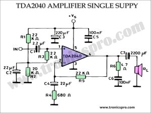
![TDA2040 Power Amplifier 25W Single Supply]()
TDA2040 Power Amplifier 25W Single Supply
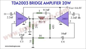
![TDA2003 Bridge Amplifier 20W circuit - Tronicspro]()
TDA2003 Bridge Amplifier 20W circuit - Tronicspro
![150W Audio Amplifier Circuit Diagram using TIP3055 & TIP2955]()
150W Audio Amplifier Circuit Diagram TIP3055
![150 Watt Lamp Dimmer Circuit Diagram]()
150 Watt Lamp Dimmer Circuit Diagram
![200W Power Amplifier Circuit using 2SC5200 & 2SA1943]()
200W Amplifier Circuit using 2SC5200 and 2SA1943 Transistors
![100 Watts LM3886 Amplifier Circuit Diagram]()
100 Watts LM3886 Amplifier Circuit Diagram


I am trying to make the circuit “OCL Amplifier Circuit Diaram using TIP31 & TIP32”. I did not succeed so far. I am about to just restart, i could have made a mistake. Looking at the schematics it occured to me that the pinout for the C1815 Transistor is in the schematic with the arrow pointing inside, like a pnp transistor. In the datasheet of the C1815 Transistor i see it is a npn transistor pointing the arrow outwards. This confuses me> This also is so the case for the a1015 transistor but the inversed. Would this be the reason for my fail to build the circuit?