Introduction
In the world of audio electronics, power amplifiers play a vital role in enhancing the sound quality and amplifying the audio signals to deliver a rich and immersive listening experience. In this article, we will explore the 50W stereo power amplifier circuit diagram that utilizes the STK4141 IC, a highly efficient and versatile integrated circuit.
STK4141 IC Specifications:
The STK4141 is an integrated circuit designed for audio power amplification applications. Developed by Sanyo, it offers a range of outstanding features and specifications that make it a popular choice among audio enthusiasts. Some key specifications of the STK4141 IC include:
- Power Rating: The STK4141 IC can deliver a power output of up to 25 watts per channel, making it suitable for medium-sized audio setups.
- High Efficiency: With its built-in efficient power supply circuit, the STK4141 IC offers excellent power efficiency, ensuring minimal power wastage.
- Wide Frequency Response: The IC exhibits a wide frequency response range, making it ideal for reproducing various audio frequencies accurately.
- Low Distortion: The STK4141 is designed to minimize distortion levels, resulting in crisp and clear audio output.
- Built-in Protection Circuitry: The IC incorporates protective mechanisms to safeguard against short circuits, thermal overload, and other potential electrical faults, ensuring the longevity of the amplifier circuit.
Stereo Power Amplifier Circuit Diagram using STK4141
This audio amplifier circuit can be built using a few basic components with the main STK4141 IC. The circuit diagram of this audio amplifier circuit project is shown below.

24V Power Supply Circuit Diagram


More Circuit Layouts


You can download the datasheet of STK4141 IC for a detailed description, pinout, features, dimension, and specifications.
Components List of Stereo Power Amplifier Circuit STK4141
Following is the list of all components used in this audio amplifier circuit project:
- STK4141 IC x 1
- 56k Resister x 4
- 2.2k Resister x 4
- 1k Resister x 4
- 560R Resister x 2
- 100R Resister x 2
- 4.7R Resister x 2
- 220uf Capacitor
- 2.2uf Capacitor x 2
- 100uf Capacitor x 3
- 47uf Capacitor x 2
- 10uf Capacitor x 3
- 0.1uf (100nf) Capacitor x 2
- 470pf Capacitor x 2
- Power Supply +/- 12V to 39V Max
- PCB Gerber Filer – Fore complete physical project detail or PCB printing, visit this site.
Explanation of 50W Stereo Audio Amplifier Circuit STK4141
Now let’s dive into the 50W stereo power amplifier circuit diagram that utilizes the powerful STK4141 IC. This circuit is fairly simple yet highly efficient, making it a preferred choice for several DIY audio projects. The circuit diagram consists of the following components:
- STK4141 IC: This serves as the main amplification component, delivering an impressive 25W of power output per channel.
- Power Supply: A suitable power supply circuit needs to be incorporated to provide the necessary power to the amplifier circuit. It is recommended to use a dual power supply configuration (+/- 26Vcc) for better performance. The maximum limit of power supply is +/- 39Vcc
- Input Stage: The audio input signals are fed into the amplifier circuit via coupling capacitors to remove any DC offset and ensure proper transmission of audio signals.
- Feedback Network: A well-designed feedback network is implemented to regulate the gain and stability of the amplifier.
- Output Stage: The amplified audio signals are then delivered to the output stage, which drives the connected speakers or other audio output devices. The recommended load resistance is 8 ohms.
Conclusion
The 50W stereo amplifier circuit diagram using STK4141 IC provides an efficient and robust solution for audio power amplification needs. With its excellent power output, wide frequency response, and low distortion levels, it delivers superior audio quality suitable for various applications. Whether you are an electronics enthusiast or a professional audio system designer, incorporating this circuit in your projects will undoubtedly enhance the audio experience. Upgrade your audio setup with the 50W stereo amplifier circuit using the reliable and versatile STK4141 IC, and enjoy the immersive soundscape it brings.
More projects, You may like:
- Video Transmitter DIY Homemade FM Radio Transmitter
- Adjustable Power Supply DIY Battery Charger
- 12V-220V 500 Watt inverter DIY Homemade
- 12V-220V H-Bridge Inverter DIY Homemade
- MPPT Solar Charge Controller DIY Homemade
- 18650 battery bank free charge protection module
- D718 B688 Bass Amplifier Homemade DIY
- C5200 Bass Amplifier DIY Homemade with Volume
- DIY LA4440 bass amplifier homemade
- C5200 A1943 TDA2030 Amplifier DIY Homemade
For more project and circuit diagrams, you can go through the Schematics in the main menu where you can find many interesting projects and circuit diagrams like audio amplifier circuits, voltage booster circuit, battery charger circuit and timer circuits etc., which are all beginner circuit projects. Feel free to check them out!

Thank you for visiting the article.
You may also like:
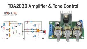
![TDA2030 Amplifier with Tone Control Circuit Diagram]()
TDA2030 Amplifier with Tone Control Circuit Diagram
![1400W Audio Power Amplifier Circuit using 2SC2912 & 2SA1216]()
1400W Audio Power Amplifier Circuit Diagram using 2SC2922 & 2SA1216
![Bass Booster Circuit Diagram using Single Transistor]()
Bass Booster Circuit Diagram using Single Transistor 2N2222
![120W Amplifier Circuit Diagram using 2SC5200 & 2SA1943 Apex Kelvin AX14]()
120W Amplifier Circuit Diagram using 2SC5200 & 2SA1943 Apex Kelvin AX14
![AM Radio Power Amplifier Circuit Diagram]()
AM Radio Power Amplifier Circuit Diagram
![Power Supply Audo-On-Off Switch Circuit]()
Power Supply Auto-On-Off Switch Circuit Diagram
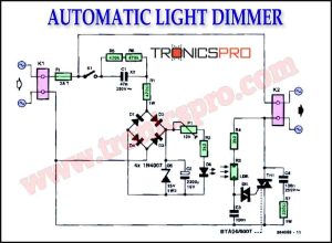
![Automatic Light Dimmer Circuit Diagram]()
Automatic Light Dimmer Circuit Diagram
![Selective Door Chime Circuit Diagram]()
Selective Door Chime Circuit Diagram