Introduction
The panoramic control circuit, also known as panning circuit, enables the user to alter the position of a single microphone input between two output channels. This functionality of 2-Channel Audio Panning Circuit is frequently used in mixing consoles within recording studios. By utilizing panning, recording engineers can achieve the effect of placing a pianist’s sound on one side of the stage and then move it to the other side.
Audio panning is a widely used technique that creates the illusion of sound moving from one speaker to another and is commonly used in music and multimedia production. A 2-channel audio panning circuit allows for two-channel stereo input to be panned or moved in a specific direction using a single IC (integrated circuit). The LM387 is a popular choice for creating this circuit as it offers low distortion, high gain, and easy to use features. This diy circuit is one of the simple electronic projects or an easy electronic projects. In this website you will find most of the circuit projects for beginners and easy electronics projects.
Circuit Diagram
of 2-Channel Audio Panning Circuit
This amplifier can be designed using a few basic components. The circuit diagram of this project is shown below.

More Circuit Layouts


Design Explanation of 2-Channel Audio Panning Circuit
The LM387 IC consists of two independent operational amplifiers, each with a gain of 2. The circuit will use one of these operational amplifiers to amplify the audio signal and the other to attenuate the signal. By adjusting the amplitudes of each channel, the signal can be panned left or right.
The circuit will have two audio inputs, with one being panned left and the other being panned right. The inputs are first passed through a high-pass filter to remove any DC voltage and then mixed together. The mixed signal is then fed into a pre-amplifier with a gain of approximately 20 dB.
The output of the pre-amplifier is then split into two channels, each of which is amplified by the operational amplifiers. By adjusting the gains of each channel, the signal can be panned left or right, with a balance control used to adjust the overall balance of the stereo output.
Conclusion of 2-Channel Audio Panning Circuit
A 2-channel audio panning circuit using the LM387 IC is a simple and effective way to add panning effects to a stereo audio signal. With a few simple adjustments to the circuit, the signal can be panned left or right, and the balance control can be used to fine-tune the overall mix. This circuit is an excellent choice for anyone looking to add professional-grade audio effects to their stereo output.
More projects, You may like:
- Video Transmitter DIY Homemade FM Radio Transmitter
- Adjustable Power Supply DIY Battery Charger
- 12V-220V 500 Watt inverter DIY Homemade
- 12V-220V H-Bridge Inverter DIY Homemade
- MPPT Solar Charge Controller DIY Homemade
- 18650 battery bank free charge protection module
- D718 B688 Bass Amplifier Homemade DIY
- C5200 Bass Amplifier DIY Homemade with Volume
- DIY LA4440 bass amplifier homemade
- C5200 A1943 TDA2030 Amplifier DIY Homemade

You may also like:
![150W Amplifier Circuit using Sanken 2SC2922]()
150W HiFi Amplifier Circuit using Sanken 2SC2922 & 2SA1216
![450W Power Amplifier Circuit Diagram using 2SC2922 & 2SA1216]()
450W Power Amplifier Circuit Diagram using 2SC2922 & 2SA1216 Sanken
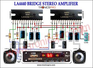
![LA4440 Bridge Stereo Amplifier Circuit Diagram]()
LA4440 Bridge Stereo Amplifier Circuit Diagram
![800W Audio Amplifier Circuit Diagram C5200 A1943]()
800W Power Amplifier Circuit C5200 A1943
![Audio Mixer Preamplifier with Tone Control Circuit]()
Audio Mixer Preamplifier with Tone Control Circuit
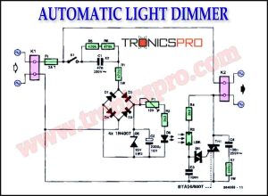
![Automatic Light Dimmer Circuit Diagram]()
Automatic Light Dimmer Circuit Diagram
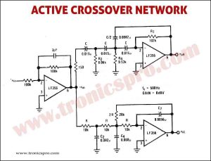
![Active Crossover Network Circuit Diagram]()
Active Crossover Network Circuit Diagram
![STK4141 Stereo Amplifier Circuit Diagram 50W]()
STK4141 Stereo Amplifier Circuit Diagram