Introduction

An audio amplifier is a crucial component in any sound system, as it amplifies the low-power audio signal and boosts it to a level suitable for driving speakers. In this article, we will discuss a 150W audio amplifier circuit diagram that utilizes the TIP142 and TIP147 power transistors. These transistors are known for their high power-handling capability and excellent performance, making them ideal for audio applications.
Specifications of TIP142, TIP147, and TIP41
- TIP142: The TIP142 is a PNP power transistor that can handle a maximum collector-emitter voltage (VCEO) of 100V. It has a maximum collector current (IC) rating of 10A and a power dissipation (PD) of 125W. This transistor is specifically designed for high-voltage audio amplifier applications.
- TIP147: The TIP147, on the other hand, is an NPN power transistor that complements the TIP142. It shares similar specifications but with a reversed polarity. It can also handle a maximum VCEO of 100V, IC of 10A, and PD of 125W. The TIP147 is commonly used as the output transistor in audio amplifier circuits.
- TIP41: The TIP41 is an NPN epitaxial silicon power transistor with a maximum VCEO of 60V, IC of 6A, and PD of 65W. Although not directly used in this 150W audio amplifier circuit, it is often employed in the driver stage to provide proper signal amplification.
150W Audio Amplifier Circuit Diagram
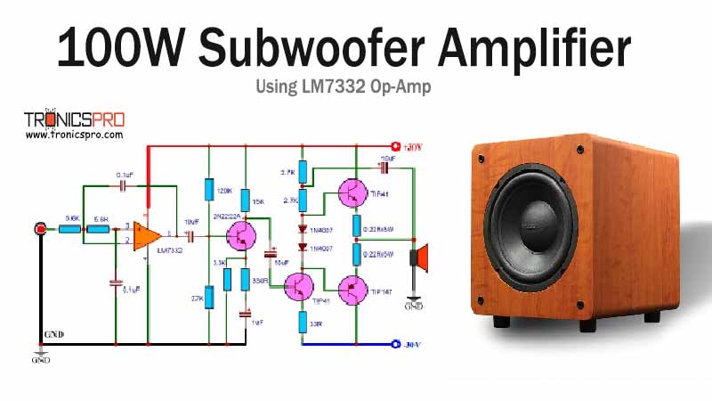
This project can be built using a few basic components. The circuit diagram of this project is shown below.

Caution: Website contains information on high voltage circuits. Proceed at your own risk, ensuring proper knowledge and precautionary measures to prevent electric shock or injury.
More Circuit Layouts


Components List of 150W Audio Amplifier Circuit Diagram
Following is the list of all components used in this project:
- TIP142 Transistor x 2
- TIP147 Transistor x 2
- TIP41 Transistor x 1
- BC556 Transistor x 2
- 0.33Ω Resisters x 4
- 3.3k Resister x 2
- 33Ω Resister x 1
- 1.5k Resister x 1
- 2.2k Resister x 1
- 470Ω Resister x 1
- 22k Resister x 2
- 100k Potentiometer x 1
- 10uF Capacitor x 2
- 100pF Capacitor x 2
- 100uF Capacitor x 1
- 470pF Capacitor x 1
- 1N4007 Diode x 2
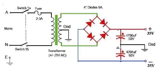
- ±30V Power supply
Working Explanation of 150W Audio Amplifier Circuit Diagram
Now, let’s move on to the 150W audio amplifier circuit using the TIP142 and TIP147 power transistors. The circuit is designed for a stereo application, meaning two identical circuits will be required for a complete audio system. However, we will focus on a single channel schematic for simplicity.
The circuit consists of two main stages – the pre-amplifier stage and the power amplifier stage. The preamplifier stage is responsible for amplifying the low-level audio signal from a source such as a microphone or a CD player. It utilizes a pair of BC556 transistors as a voltage amplifier.
The amplified signal from the preamplifier stage is then fed into the power amplifier stage, which employs the TIP142 and TIP147 power transistors. The power transistors work in a complimentary push-pull configuration, allowing efficient amplification of the audio signal.
The TIP142 and TIP147 power transistors are capable of handling high currents and dissipating significant power, making them suitable for driving speakers with a power rating of up to 150W. With proper heat sinks and power supply, this circuit can deliver high-quality audio with minimal distortion.
Conclusion
The 150W audio amplifier circuit using TIP142 and TIP147 power transistors is a reliable and efficient solution for high-power audio amplification. The TIP142 and TIP147 transistors, along with the TIP41 driver transistor, provide excellent performance and power-handling capabilities.
With proper implementation and component selection, this circuit can deliver exceptional audio quality, making it an ideal choice for various applications, including home theaters, sound systems, and live performances. Ensure to follow the circuit diagram and specifications of the transistors for optimal results.
More projects, You may like:
- Video Transmitter DIY Homemade FM Radio Transmitter
- Adjustable Power Supply DIY Battery Charger
- 12V-220V H-Bridge Inverter DIY Homemade
- DIY LA4440 bass amplifier homemade
For more project and circuit diagrams, you can go through the Schematics in the main menu where you can find many interesting projects and circuit diagrams like audio amplifier circuits, voltage booster circuit, and timer circuits etc. Feel free to check them out!

Thank you for visiting the article.


Dear Sir,
What should be the Power Transformer Amp rating ?
Thanks in anticipation.
3 to 5 amp can have enough power.
Is it possible to increase the power, maybe from 150watts to 400watts