

Introduction
In the world of audio amplifiers, power and quality are two crucial factors that audiophiles prioritize. With technological advancements, audio enthusiasts are constantly on the lookout for robust and high-performance amplifier circuit diagrams. In this article, we will explore a 150W audio amplifier circuit diagram that utilizes dual 2N3055 transistors in the output stage, along with 2N3569 and 2N4355 transistors in the driver stage, and MPS6533 in the preamplifier stage. This amplifier promises to deliver exceptional power and sound quality, ensuring an immersive audio experience.
Specifications of 2N3055 Transistor:
Before we discuss the circuit diagram, let’s take a moment to explore the specifications of the 2N3055 transistor, which plays a significant role in the amplifier’s output stage:
- Maximum Collector-Emitter Voltage: 70V
- Maximum Collector Current: 15A
- Maximum Power Dissipation: 115W
- Transition Frequency: 2.5 MHz
- Gain (hFE): 20 to 70
Amplifier Circuit Diagram 2N3055
This project can be built using a few basic components. The circuit diagram of this project is shown below.


Caution: Website contains information on high voltage circuits. Proceed at your own risk, ensuring proper knowledge and precautionary measures to prevent electric shock or injury.
More Circuit Layouts


Components List of Amplifier Circuit Diagram 2N3055
Following is the list of all components used in this project:
- 2N3055 Transistor x 2
- 2N3509 Transistor x 2
- 2N4355 Transistor x 1
- MPS6533 Transistor x 1
- 100k Resister x 1
- 270k Resister x 1
- 2.2K Resister x 2
- 150k Resister x 1
- 100 Ohms Resister x 1
- 3.9k Resister x 1
- 10k Resister x 2
- 1k Resister x 1
- 3.9k Resister x 1
- 20 Ohms Resister x 2
- 390 Ohms Resister x 1
- 120 Ohms / 2W Resister x 2
- 0.5 Ohms / 5W Resister x 2
- 10 Ohms / 2W Resister x 1
- 4.7uF Capacitor x 1
- 47uF/50V Capacitor x 2
- 100uF Capacitor x 1
- 10uF Capacitor x 1
- 220uF Capacitor x 2
- 200pF Capacitor x 1
- 2200uF Capacitor x 1
- 0.05uF Capacitor x 1
- CD0014 Diode x 2
- 30V Single Power Supply
- Speaker 4 Ohms
Explanation of Amplifier Circuit Diagram 2N3055
Now, let’s move on to the circuit diagram and understand how this amplifier harnesses the potential of the 2N3055 transistor and other complementary components.
The circuit diagram showcases an optimized design to achieve a power output of 150W. The 2N3055 transistors in the output stage provide ample current handling capacity, ensuring minimal distortion even at high volumes. These transistors can handle up to 15A of current and are capable of dissipating power up to 115W, making them ideal for this application.
In the driver stage, we employ the 2N3569 and 2N4355 transistors. These transistors facilitate efficient signal amplification and ensure seamless signal transfer between the preamplifier and output stage. Their robust performance capabilities contribute to the overall sound quality of the amplifier.
The preamplifier stage features the MPS6533 transistor, which plays a vital role in amplifying the input signal from a source such as a microphone or a music player. With its high gain characteristics, the MPS6533 transistor ensures that even weak signals are amplified adequately before being fed into the driver and output stages.
Conclusion
The 150W audio amplifier circuit diagram detailed in this article harnesses the power and performance of the dual 2N3055 transistors in the output stage, along with the 2N3569, 2N4355 transistors in the driver stage, and the MPS6533 transistor in the preamplifier stage. By utilizing these high-quality and capable components, this amplifier promises a robust and immersive audio experience.
The optimized design of this amplifier ensures a power output of 150W while maintaining exceptional sound quality. Whether you are a music enthusiast, a party host, or an audio professional, this amplifier circuit diagram provides a reliable and efficient solution for your audio amplification needs. Upgrade your sound system with this 150W audio amplifier employing the dual 2N3055 transistors, and treat yourself to a new level of audio performance.
More projects, You may like:
- Video Transmitter DIY Homemade FM Radio Transmitter
- Adjustable Power Supply DIY Battery Charger
- 12V-220V 500 Watt inverter DIY Homemade
- MPPT Solar Charge Controller DIY Homemade
- DIY LA4440 bass amplifier homemade
For more project and circuit diagrams, you can go through the Schematics in the main menu where you can find many interesting projects and circuit diagrams like audio amplifier circuits, voltage booster circuit, and timer circuits. Feel free to check them out!

Thank you for visiting the article.
You may also like:
![300W Amplifier Circuit Diagram for Subwoofer]()
300W Amplifier Circuit for Subwoofer | DIY Homemade
![DIY Beginners Power Amplifier Circuit Diagram using 2SC5200 NE5532]()
DIY Beginners Power Amplifier Circuit using 2SC5200 & NE5532
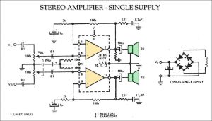
![Stereo Amplifier Single Supply Circuit Diagram]()
Stereo Amplifier Single Supply Circuit Diagram
![12V Variable Power Supply Circuit Diagram]()
Simple Variable 12V Power Supply Circuit Diagram
![Stereo Amplifier TDA7297 Dual-Bridge Circuit Diagram]()
Stereo Amplifier TDA7297 Dual-Bridge Circuit
![100W PNP Power Amplifier Circuit Diagram Homemade]()
100W PNP Power Amplifier Circuit Diagram DIY Homemade
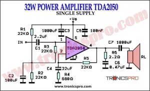
![32W Power Amplifier TDA2050 Single Supply Circuit Diagrm]()
32W Power Amplifier TDA2050 Single Supply
![Multi Color Led Circuit Diagram]()
Multi Color Led Circuit Diagram


Can I use tip 41 in place of the mps6533