

Introduction
Building your own DIY bass amplifier can be a great way for beginners to learn about electronics and to develop a personalized sound system. The 13003 DIY Bass Amplifier using 13003 X 6 transistors in parallel and one D882 transistor with an MP3 player as the input source is a great project for enthusiasts who want to have a deeper understanding of how an amplifier works.
This project produces a powerful and clean bass sound, making it ideal for music lovers who want to enjoy listening to their favorite songs with a high-quality sound.
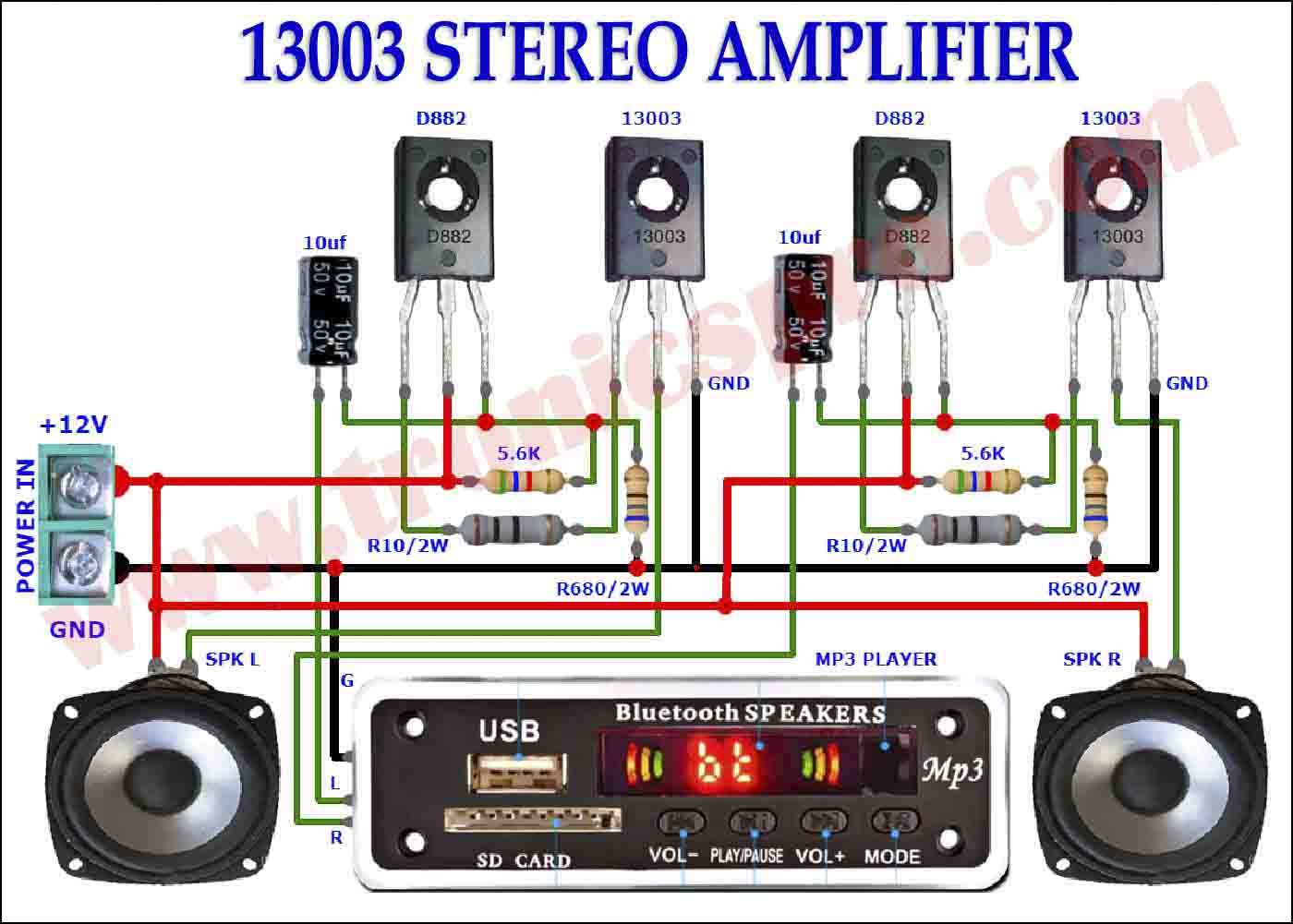
Circuit Diagram
of 13003 DIY Bass Amplifier
The 20A Current Monitor Circuit can be designed using a few basic components. The circuit diagram of this project is shown below.

Components List of 13003 DIY Bass Amplifier
To build this DIY Bass Amplifier, you need the following components:
- 13003 NPN transistors in parallel x 6
- D882 NPN transistor x 1
- 10 μF capacitor x 1
- 10 ohms resistor x 1
- 680 ohms resistors x 1
- 5.6k ohms resistors x 1
- 10k ohms resisters for mp3 player input source x 2
- 10k Potentiometer x 1
- 4 ohms speaker
- MP3 player optional
More Circuit Layouts


Conclusion
The DIY Amplifier using 13003 and D882 transistors with an MP3 player as the input source is a great project for beginners and enthusiasts who want to learn about electronics and develop their personalized sound system. This amplifier produces a powerful and clean bass sound, making it ideal for music lovers who want to enjoy their favorite songs with a high-quality sound. By following the steps according to the circuit diagram provided above, you can easily construct this bass amplifier and enjoy music with the high-quality sound of your choice.
More projects, You may like:
- Video Transmitter DIY Homemade FM Radio Transmitter
- Adjustable Power Supply DIY Battery Charger
- 12V-220V 500 Watt inverter DIY Homemade
- 12V-220V H-Bridge Inverter DIY Homemade
- MPPT Solar Charge Controller DIY Homemade
- 18650 battery bank free charge protection module
- D718 B688 Bass Amplifier Homemade DIY
- C5200 Bass Amplifier DIY Homemade with Volume
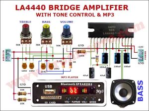
- DIY LA4440 bass amplifier homemade
- C5200 A1943 TDA2030 Amplifier DIY Homemade

You may also like:
![300W Audio Amplifier Circuit using 2SC5200 & 2SA1943 APEX AX11TEF]()
300W Audio Amplifier Circuit Diagram using 2SC5200 & 2SA1943 APEX AX11TEF
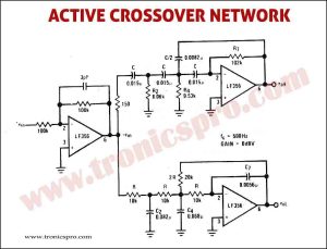
![Active Crossover Network Circuit Diagram]()
Active Crossover Network Circuit Diagram
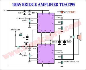
![100W Bridge Amplifier TDA7295 Circuit Diagram]()
100W Bridge Amplifier TDA7295 Circuit Diagram
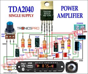
![30W TDA2040 Power Amplifier Circuit Diagram]()
30W TDA2040 Power Amplifier Circuit Diagram
![Top TDA2030 Amplifier Circuit Diagrams Tronicspro]()
Top TDA2030 Amplifier Circuit Diagrams Tronicspro
![Attenuator Limiter Circuit Diagram]()
Attenuator Limiter Circuit Diagram
![Digital Audio High-end Oscillator Circuit]()
Digital Audio High-end Oscillator Circuit
![TDA7294 Power Amplifier Circuit 120W - Tronicspro]()
TDA7294 Power Amplifier Circuit 120W - Tronicspro


That circuit won’t make any sound as it is drawn. Please add a collector load resistor. You’re talking about it, why not just add it to to the diagram?
Why do you even post something this? This isn’t even an amplifier. It’s just random components. Firstly, the input stage seems to be an emitter follower. This won’t help you at all. You want to amplify voltage, not current here. The rest of the circuit is wired incorrectly. You have the bases wired to ground and the signal comes in on the emitter. What’s that supposed to achieve? The base will never go higher than the emitter and you will have zero signal out. There’s no way you built or even simulated this.