Introduction
In the world of audio amplification, power and clarity are two key factors that enthusiasts strive for. With the advancements in technology, the demand for high-power audio amplifiers has increased exponentially. This article aims to provide a comprehensive overview of a 100W audio amplifier circuit diagram using 2SC5200 and 2SA1943 transistors in the output section, 2N5551 and 2N5401 in the driver section, and 2N5401 transistors in the preamplifier section.
Specifications of Transistors:
- 2SC5200:
- Maximum Collector-Base Voltage: 150V
- Maximum Collector-Emitter Voltage: 150V
- Maximum Collector Current: 15A
- Power Dissipation: 150W
- Transition Frequency: 30MHz
- 2SA1943:
- Maximum Collector-Base Voltage: 230V
- Maximum Collector-Emitter Voltage: 230V
- Maximum Collector Current: 15A
- Power Dissipation: 140W
- Transition Frequency: 30MHz
- 2N5551:
- Maximum Collector-Base Voltage: 160V
- Maximum Collector-Emitter Voltage: 140V
- Maximum Collector Current: 600mA
- Power Dissipation: 625mW
- Transition Frequency: 150MHz
- 2N5401:
- Maximum Collector-Base Voltage: 160V
- Maximum Collector-Emitter Voltage: 150V
- Maximum Collector Current: 600mA
- Power Dissipation: 625mW
- Transition Frequency: 300MHz
100W Audio Amplifier Circuit Diagram using 2SC5200 & 2SA1943
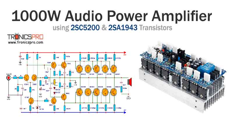
This project can be built using a few basic components. The circuit diagram of this project is shown below.
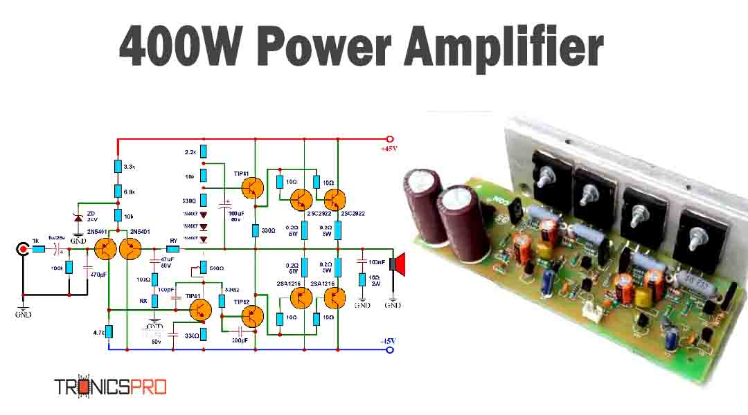
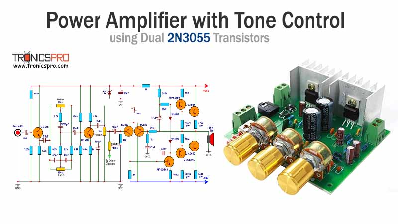
More Circuit Layouts






Components List of Audio Amplifier Circuit using 2SC5200 & 2SA1943
Following is the list of all components used in this project:
- 2SC5200 transistor x 1
- 2SA1943 transistor x 1
- 2N5551 transistor x 2
- 2N5401 transistor x 3
- 1N4148 diode x 2
- 1k Resister x 1
- 47k Resister x 2
- 4.7k Resister x 2
- 100k Resister x 1
- 2.2k Resister x 1
- 10Ω Resister x 1
- 0.22Ω/5W Resister x 2
- 10µF Capacitor x 1
- 1µF Capacitor x 2
- 1N4148 Diode x 1
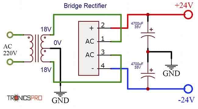
- ±24V Symmetrical Power Supply
- 4Ω/50W Speaker
Explanation of Audio Amplifier Circuit using 2SC5200 & 2SA1943
The 100W audio amplifier circuit consists of a series of transistors strategically placed to ensure efficient and powerful amplification. The output section utilizes the 2SC5200 and 2SA1943 transistors, known for their high power handling capabilities and excellent audio quality. These transistors are capable of delivering clean and distortion-free power to the speakers.
The driver section of the circuit employs the 2N5551 and 2N5401 transistors. These transistors act as intermediary devices between the preamplifier and the output transistors, providing the necessary amplification and signal conditioning. The 2N5551 is an NPN transistor, while the 2N5401 is a complementary PNP transistor, creating a balanced and stable driver section.
The preamplifier section uses 2N5401 transistors, which are high-gain PNP transistors known for their excellent low-noise performance. This section ensures that the audio signal from the input source is properly amplified and prepared for the driver section.
Conclusion
The 100W audio amplifier circuit utilizing the 2SC5200, 2SA1943, 2N5551, and 2N5401 transistors offers excellent power output, clarity, and low distortion. The strategic placement of these transistors in the output, driver, and preamplifier sections ensures efficient signal amplification and smooth audio reproduction. Whether you’re an audio enthusiast or simply looking to enhance your audio system, this circuit diagram provides a reliable and powerful solution.
More projects, You may like:
- Video Transmitter DIY Homemade FM Radio Transmitter
- Adjustable Power Supply DIY Battery Charger
- 12V-220V 500 Watt inverter DIY Homemade
- MPPT Solar Charge Controller DIY Homemade
- DIY LA4440 bass amplifier homemade
For more project and circuit diagrams, you can go through the Schematics in the main menu where you can find many interesting projects and circuit diagrams like audio amplifier circuits, voltage booster circuit, battery charger circuit and timer circuits etc., which are all beginner circuit projects. Feel free to check them out!

Thank you for visiting the article.






Can i use 2n3055 and 2n2955 power transistor
Yes, you can use.
Can i use 2n3055 and 2n2955 power transistor. Can i add 2 more pair of power transistor to increase output?
Have you built this? I tried several times and it did not work. Has a fainted sound from the speaker. Some how this scheme switch off NPN power transistor when working.
Got it working by changing the entry transistors to 2n5551(NPN), and swapping the emitter and collector.
Thank you.
Hola me gustaría saber si funciona y confiable este diagrama ha sido probado ?
what is the max. input voltage?
I want to build one, but I would like to know the frequency response and harmonic distortion if possible, thanks.