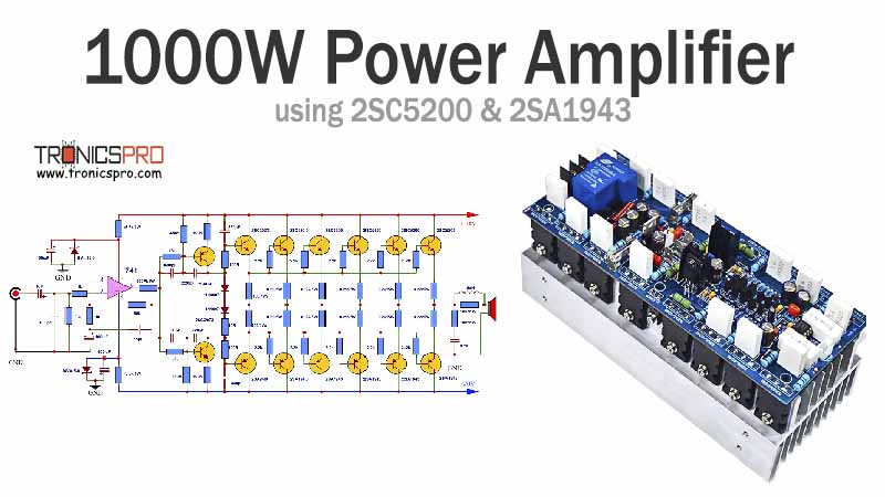
Introduction
In the field of audio amplification, a 1000W amplifier circuit using 2SC5200 and 2SA1943 transistors in the output stage and a 741 IC in the preamplifier stage is a popular configuration used to achieve high power output with high fidelity. This circuit is capable of driving loudspeakers or subwoofers in audio systems, making it suitable for various applications like home theater systems, musical performances, or PA systems.
To meet this need, amplifier circuits capable of delivering significant wattage have become a necessity. In this article, we will explore a 1000W amplifier circuit diagram utilizing the powerful 2SC5200 and 2SA1943 transistors. These transistors are renowned for their performance, making them an ideal choice for such high-power applications.
2SC5200 Transistor Specifications:
The 2SC5200 is a high-power NPN transistor designed for audio and general-purpose amplifier applications. It boasts a maximum collector dissipation of 150 watts and can handle a collector current of up to 15 amperes. This transistor also features a high current gain, typically ranging from 55 to 160. With its excellent linearity and low distortion characteristics, the 2SC5200 is an excellent choice for audio amplification.
2SA1943 Transistor Specifications:
Complementing the 2SC5200, the 2SA1943 is a PNP transistor that shares similar high-power characteristics. It can handle a maximum collector dissipation of 150 watts and a collector current of up to 15 amperes, making it an ideal match for the 2SC5200. Like its counterpart, the 2SA1943 also features a high current gain, typically ranging from 55 to 160. The combination of these transistors ensures optimal performance and reliability in the amplifier circuit.
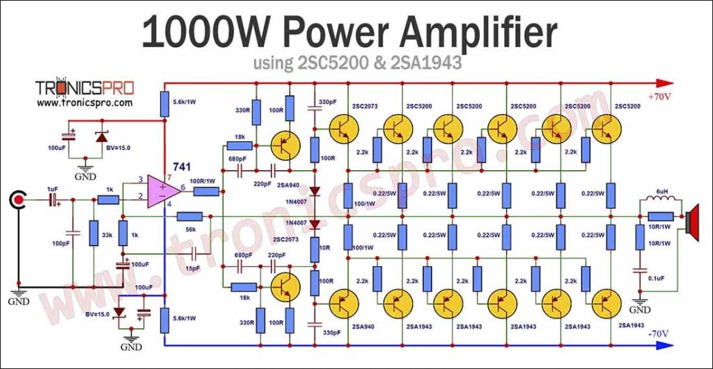
1000W Amplifier Circuit Diagram using 2SC5200 & 2SA1943
This project can be built using a few basic components. The circuit diagram of this project is shown below.
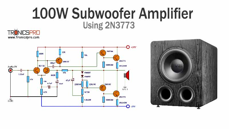
More Circuit Layouts




Components List of 1000W Amplifier Circuit Diagram using 2SC5200
Following is the list of all components used in this project:
- 2SC5200 Transistor x 5
- 2SA1943 Transistor x 5
- 2SA940 Transistor x 2
- 2SC2073 Transistor x 2
- 741 IC OPAMP x 1
- 33k Resister x 1
- 1k Resister x 2
- 5K6 Resister x 2
- 56k Resister x 1
- 100R Resister x 7
- 18k Resister x 2
- 330R Resister x 2
- 10R Resister x 3
- 2K2 Resister x 10
- 0R22 Resister x 10
- 1uF Capacitor x 1
- 100pF Capacitor x 1
- 100uF Capacitor x 3
- 15pF Capacitor x 1
- 680pF Capacitor x 2
- 220pF Capacitor x 2
- 330pF Capacitor x 2
- 0.1uF Capacitor x 1
- 1N4007 Diode x 2
- 1N5245B Diode x 2
- 6uH Coil x 1
- Speaker 4 ohms
- 50V-70V Power Supply
Explanation of 1000W Amplifier Circuit using 2SC5200
The 1000W amplifier circuit can be divided into two main stages: the preamplifier stage and the power amplifier stage.
Preamplifier stage:
The preamplifier stage serves the purpose of conditioning the input audio signal. It consists of a 741 operational amplifier, which is a commonly used IC for audio preamplification due to its low noise and high gain characteristics. The input audio signal is coupled to the amplifier through a coupling capacitor to block any DC component present. The gain of the amplifier can be adjusted by selecting appropriate resistor values, which helps in matching the input signal level to the output power amplifier stage. This preamplified signal is then fed to the power amplifier stage.
Power amplifier stage:
The power amplifier stage is responsible for amplifying the preamplified audio signal to a level that can sufficiently drive the loudspeakers or subwoofers. This stage uses 2SC5200 and 2SA1943 transistors, which are high-power, high-voltage, and high-current devices capable of handling the large power requirements.
Amplifier Circuit Diagram:
The 1000W amplifier circuit diagram integrates the 2SC5200 and 2SA1943 transistors to deliver exceptional audio quality. The circuit is designed for a symmetric power supply and features a dual-channel configuration to enhance stereo audio reproduction. The circuit incorporates multiple stages of amplification, starting with the input stage, followed by the driver stage, and culminating in the output stage. This comprehensive design ensures a clean, high-power output suitable for demanding audio applications.
The power supply section of the amplifier circuit diagram includes a rectifier bridge that converts the AC voltage into DC, ensuring an adequate power supply for the amplifier. Additionally, the circuit employs various capacitors and resistors to filter and stabilize the input and output signals, reducing unwanted noise and distortion. The overall design of the circuit is reliable and has an efficient performance.
Conclusion of 1000W Amplifier Circuit using 2SC5200
The 1000W amplifier circuit diagram utilizing the 2SC5200 and 2SA1943 transistors provides a robust solution for high-power audio amplification. Both transistors offer remarkable specifications, ensuring optimum performance and reliability in such demanding applications. This circuit enables audiophiles to create powerful audio systems capable of delivering a captivating and immersive experience. By leveraging the power of these transistors, enthusiasts can enjoy high-fidelity sound reproduction like never before.
More projects, You may like:
- Video Transmitter DIY Homemade FM Radio Transmitter
- Adjustable Power Supply DIY Battery Charger
- 12V-220V 500 Watt inverter DIY Homemade
- 12V-220V H-Bridge Inverter DIY Homemade
- MPPT Solar Charge Controller DIY Homemade
- 18650 battery bank free charge protection module
- D718 B688 Bass Amplifier Homemade DIY
- C5200 Bass Amplifier DIY Homemade with Volume
- DIY LA4440 bass amplifier homemade
- C5200 A1943 TDA2030 Amplifier DIY Homemade
For more project and circuit diagrams, you can go through the Schematics in the main menu where you can find many interesting projects and circuit diagrams like audio amplifier circuits, voltage booster circuit, battery charger circuit and timer circuits etc., which are all beginner circuit projects. Feel free to check them out!

Thank you for visiting the article.









The diagram is not so clear please
Download the 2nd circuit image. Right click over image & select ‘open in new window’ then again right click and save image. Its already clear.