Introduction
The TL494 Pulse-Width Modulation (PWM) Control IC is a widely used integrated circuit designed for efficient switching power supply control. Developed originally by Texas Instruments, it provides all the essential building blocks to implement a regulated power supply, inverter, or DC-DC converter with minimal external components. Because of its flexibility, the TL494 has become a standard device in power electronics, particularly in SMPS (Switched-Mode Power Supplies) and DC motor control circuits.
The TL494 integrates a fixed-frequency oscillator, error amplifiers, a dead-time control comparator, a PWM comparator, and an output control circuit into a single 16-pin package. Its ability to handle both single-ended and push-pull configurations makes it suitable for a wide variety of topologies, such as forward, flyback, and half-bridge converters. This versatility helps reduce design complexity and cost.
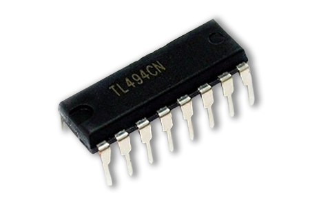
TL494 PWM Control Circuitry IC
One of the reasons the TL494 remains popular is its robust performance, wide input voltage range, and high degree of customization. It allows designers to fine-tune parameters like duty cycle, dead time, and output mode, making it adaptable for applications from small DC-DC converters to high-power inverters and UPS systems.
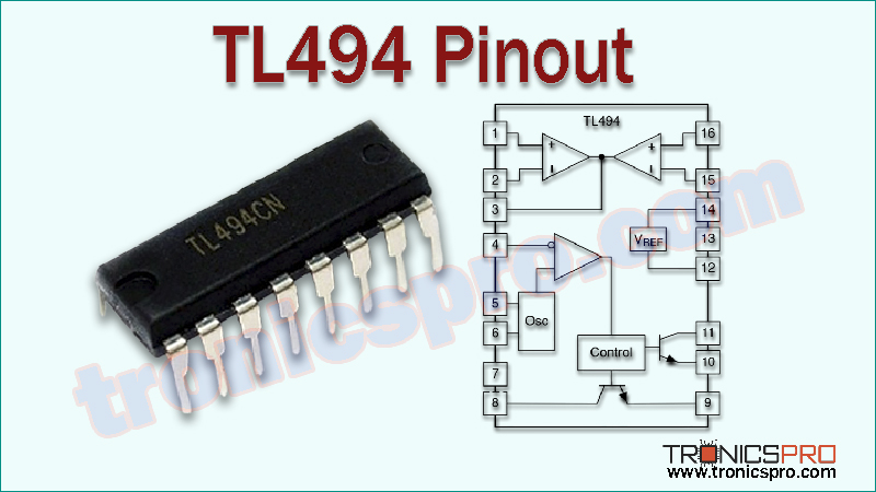
TL494 Pinout
TL494 Key Features
- Internal 5V reference regulator (±1%) for precision control.
- On-chip oscillator with adjustable frequency.
- Two error amplifiers for voltage and current regulation.
- Pulse-steering flip-flop for push-pull or parallel operation.
- Adjustable dead-time control for safe switching.
- Wide supply voltage range (7V to 40V).
- High duty cycle capability up to 100%.
- Compatible with single-ended or push-pull configurations.
- Available in DIP-16 and SOIC-16 packages.
TL494 Specifications/Characteristics
- Supply Voltage (Vcc): 7V to 40V
- Reference Output Voltage: 5V ±1%
- Oscillator Frequency Range: Up to 300 kHz (typical ~100 kHz)
- Output Current (per output): 200 mA (peak)
- Output Type: Totem-pole / open-collector (configurable)
- Operating Temperature Range: 0°C to +70°C (commercial), -40°C to +85°C (industrial grade)
- Duty Cycle Range: 0% to 100%
- Package Options: PDIP-16, SOIC-16, TSSOP-16
Note: DATASHEET DOWNLOAD button is provided end of this article.
Pin Configuration of TL494 PWM Control IC
| Pin# | Pin Name | Pin Description |
|---|---|---|
| 1 | 1IN+ | Non-inverting input of error amplifier 1 |
| 2 | 1IN– | Inverting input of error amplifier 1 |
| 3 | FEEDBACK | Output of error amplifier 1, connected to PWM comparator |
| 4 | DTC | Dead-time control input |
| 5 | CT | Timing capacitor for oscillator |
| 6 | RT | Timing resistor for oscillator |
| 7 | GROUND | Ground reference |
| 8 | C1 | Collector output of transistor 1 |
| 9 | E1 | Emitter output of transistor 1 |
| 10 | E2 | Emitter output of transistor 2 |
| 11 | C2 | Collector output of transistor 2 |
| 12 | Vcc | Supply voltage (7V – 40V) |
| 13 | OUTPUT CTRL | Output control input (toggles single-ended or push-pull operation) |
| 14 | REF OUT | 5V reference voltage output |
| 15 | 2IN– | Inverting input of error amplifier 2 |
| 16 | 2IN+ | Non-inverting input of error amplifier 2 |
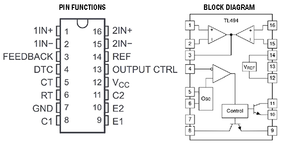
TL494 Pin Functions & Block Diagram
More Circuit Layouts


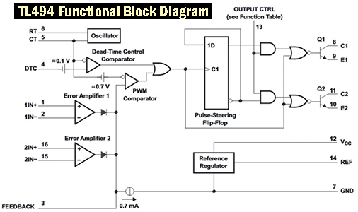
TL494 Functional Block Diagram
Key Applications of TL494 PWM Control IC
- Switched-Mode Power Supplies (SMPS).
- DC-DC Converters (step-up, step-down, and flyback topologies).
- UPS (Uninterruptible Power Supply) systems.
- Inverter circuits for solar and motor control.
- Voltage and current regulation circuits.
- DC motor speed controllers.
- Battery chargers and LED drivers.
TL494 Equivalent ICs / Alternatives
- KA7500 – Functionally equivalent PWM controller.
- SG3524 – PWM regulator IC with similar performance.
- UC3842/UC3843 – Alternative PWM controllers (single-ended).
- LM494 / LM3524D – Comparable ICs for power regulation.
- MC33025 – Dual PWM controller with similar functionality.
(The pinout for certain ICs can vary from that of the TL494).
Datasheet of TL494 PWM Control IC
Click the following Button below to download the datasheet of TL494 :
More projects, You may like:
- Video Transmitter DIY Homemade FM Radio Transmitter
- Adjustable Power Supply DIY Battery Charger
- 12V-220V 500 Watt inverter DIY Homemade
- MPPT Solar Charge Controller DIY Homemade
- DIY LA4440 bass amplifier homemade
For more project and circuit diagrams, you can go through the Schematics in the main menu where you can find many interesting projects and circuit diagrams like audio amplifier circuits, voltage booster circuit, battery charger circuit and timer circuits etc., which are all beginner circuit projects. Feel free to check them out!
Thank you for visiting the article.