Introduction
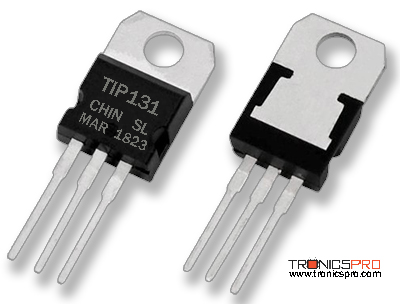
The TIP131 is a high-power NPN Darlington transistor designed for applications requiring high current gain and reliable switching. Built using a monolithic Darlington configuration, the TIP131 integrates two NPN transistors internally, providing very high current amplification (hFE ≥ 1000). This makes it an excellent choice for low input signal amplification, motor drivers, relay drivers, and medium power audio amplifier circuits.

With its TO-220 package, the TIP131 offers efficient heat dissipation and compact design suitable for power circuits. It can handle a collector current up to 8A and a power dissipation of 80W, making it capable of driving heavy loads in industrial, automotive, and consumer electronics applications.
TIP131 NPN Power Transistor
Another key advantage of the TIP131 transistor is its low saturation voltage and high durability. With a collector-emitter voltage (Vce) of 80V, the TIP131 is best suited for medium-voltage power applications where both switching speed and amplification are required. Its reliability and cost-effectiveness make it a popular choice among engineers for DC motor control, solenoid drivers, power regulators, and signal amplification systems.
TIP131 Pinout
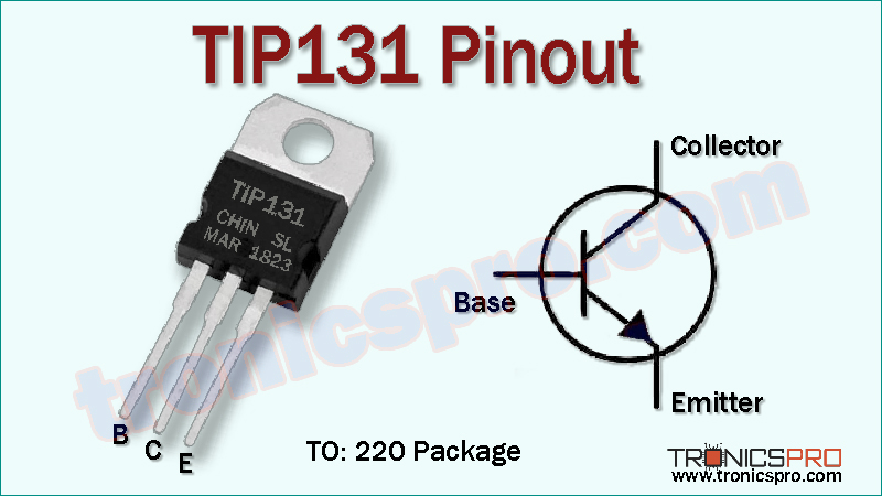
TIP131 Pin Configuration
| Pin# | Pin Name | Pin Description |
|---|---|---|
| 1 | Base (B) | Controls transistor operation |
| 2 | Collector (C) | Connected to load or power supply |
| 3 | Emitter (E) | Current output terminal |
TIP131 Transistor Key Features
- High DC current gain (hFE ≥ 1000).
- Monolithic Darlington transistor design for efficient amplification.
- High collector current rating (up to 8A).
- Compact TO-220 package with good thermal performance.
- Reliable for switching and amplification applications.
- Cost-effective and widely available.
Characteristics of TIP131 NPN Power Transistor
- Transistor Type: NPN Power Darlington
- Package: TO-220
- Collector-Emitter Voltage (Vce): 80V
- Collector-Base Voltage (Vcb): 80V
- Emitter-Base Voltage (Veb): 5V
- Collector Current (Ic): 8A
- Power Dissipation (Pd): 80W
- DC Current Gain (hFE): ≥ 1000
- Junction Temperature (Tj): 150°C (max)
- Transition Frequency (ft): 3 MHz (typical)
More Circuit Layouts


Key Applications of TIP131 NPN Power Transistor
- Audio amplifier output stages.
- Relay drivers and solenoid control.
- DC motor control and power regulation.
- Switching regulators and power supplies.
- Industrial and automotive control systems.
- Battery charger circuits.
PNP Complimentary Transistor
TIP136 is the PNP complementary transistor of TIP131.
Equivalent Transistors of TIP131
- TIP130 (100V rating, NPN Darlington)
- TIP132 (100V rating, NPN Darlington)
- BDW93C (NPN Darlington, similar specs)
- MJ11015 (high-power NPN Darlington)
(Pin configuration of some transistors mentioned above may different from TIP131).
Comparison of TIP130 vs TIP131 vs TIP132
The TIP130, TIP131, and TIP132 are all NPN Darlington power transistors in the TO-220 package, offering similar current handling capability of 8A and a maximum power dissipation of 80W. They also share a very high DC current gain (≥1000), making them excellent for high amplification and switching applications.
The main difference lies in their voltage ratings and complementary PNP pairs:
- TIP130 supports 100V and pairs with TIP135, making it suitable for general-purpose power switching.
- TIP131 has a lower Vce rating of 80V and pairs with TIP136, making it ideal for slightly lower-voltage applications where efficiency is prioritized.
- TIP132 supports the highest Vce rating of 100V, similar to TIP130, but is often preferred in high-voltage or high-power systems with its complementary TIP137.
All three are paired with their complementary PNP versions (TIP135, TIP136, TIP137) for push-pull configurations in amplifiers and motor drivers.
In short, TIP131 is best for lower-voltage circuits, while TIP130 and TIP132 are more suitable for medium to high-voltage power applications.
Datasheet of TIP131 NPN Power Transistor
Click the following Button to download the datasheet of TIP131 Transistor :
More projects, You may like:
- Video Transmitter DIY Homemade FM Radio Transmitter
- Adjustable Power Supply DIY Battery Charger
- 12V-220V 500 Watt inverter DIY Homemade
- MPPT Solar Charge Controller DIY Homemade
- DIY LA4440 bass amplifier homemade
For more project and circuit diagrams, you can go through the Schematics in the main menu where you can find many interesting projects and circuit diagrams like audio amplifier circuits, voltage booster circuit, battery charger circuit and timer circuits etc., which are all beginner circuit projects. Feel free to check them out!
Thank you for visiting the article.
You may also like:
![bc108 datasheet pinout equivalent specification application]()
BC108 Pinout, Equivalent, Application, Datasheet
![2n2369 datasheet pinout]()
2N2369 Pinout, Equivalent, Application, Datasheet
![2n3903 datasheet pinout]()
2N3903 Pinout, Equivalent, Application, Datasheet
![2n5401 datasheet pinout]()
2N5401 Pinout, Equivalent, Application, Datasheet
![BD239 NPN Transistor Datasheet]()
BD239 NPN Transistor Pinout Datasheet
![bd678 datasheet pinout]()
BD678 Pinout, Equivalent, Applications, Datasheet
![BC559 PNP Transistor Datasheet]()
BC559 PNP Transistor Pinout Datasheet
![BC640 PNP Transistor Datasheet]()
BC640 PNP Transistor Pinout Datasheet