Introduction
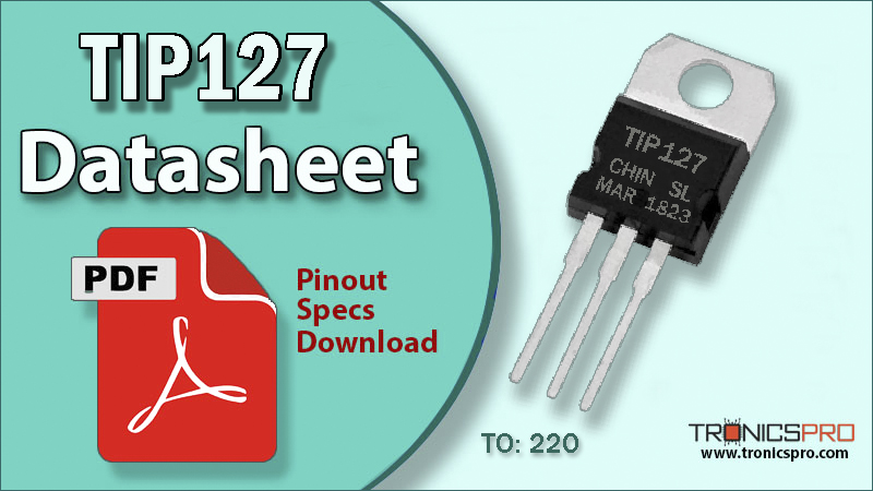
The TIP127 is a popular PNP Darlington Power Transistor designed for high current and medium voltage applications. Packaged in the TO-220 case, it is capable of handling collector currents up to 5A and collector-emitter voltages up to 100V. Thanks to its Darlington pair configuration, the TIP127 offers a very high DC current gain (hFE ≥1000), which makes it highly efficient in switching and amplification circuits without requiring additional driver stages.
This transistor is widely used in motor control, relay drivers, audio amplifier circuits, and switching regulators. Its PNP polarity allows it to function as a high-side switch, making it useful in controlling loads connected to the positive supply rail. Engineers often pair the TIP127 with its complementary NPN transistor TIP122 for push-pull amplifier stages, H-bridges, and motor driver circuits, providing balanced performance and reliability.
TIP127 PNP Transistor
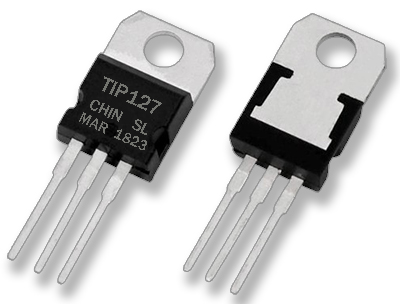
Due to its rugged design, high current capability, and integrated base-emitter resistor, the TIP127 is a highly reliable choice for both hobbyist and industrial applications. It is also a go-to option in circuits where linear amplification and power switching are required simultaneously.
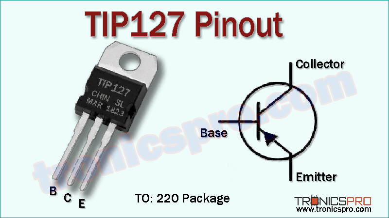
TIP127 Pinout
TIP127 Transistor Key Features
- PNP Darlington transistor with very high current gain.
- Capable of handling collector currents up to 5A.
- Supports collector-emitter voltages up to 100V.
- Integrated base-emitter resistor for stability.
- TO-220 package ensures efficient heat dissipation.
- Suitable for both switching and linear amplifier circuits.
Specifications/Characteristics of TIP127 PNP Transistor
- Transistor Type: PNP Darlington
- Collector-Emitter Voltage (Vce): 100V
- Collector-Base Voltage (Vcb): 100V
- Emitter-Base Voltage (Veb): 5V
- Continuous Collector Current (Ic): 5A
- Peak Collector Current: 8A
- DC Current Gain (hFE): ≥1000
- Power Dissipation (Ptot): 65W
- Transition Frequency (fT): 3 MHz (typical)
- Operating Temperature Range: -65°C to +150°C
- Package: TO-220
TIP127 Pin Configuration
| Pin# | Pin Name | Pin Description |
|---|---|---|
| 1 | Base (B) | Input terminal, used to trigger the transistor |
| 2 | Collector (C) | Main terminal connected to the load |
| 3 | Emitter (E) | Output terminal, typically connected to ground or negative rail |
More Circuit Layouts


Key Applications of TIP127 PNP Transistor
- Audio power amplifiers.
- Relay, solenoid, and lamp drivers.
- DC motor and stepper motor controllers.
- High-power LED driver circuits.
- Switching regulators and linear power supplies.
- H-bridge motor drivers and push-pull amplifier circuits.
NPN Complimentary Transistor
TIP122 is the NPN complementary transistor of TIP127.
Together, they are commonly used in full-bridge and amplifier circuits.
Equivalent Transistors of TIP127
- TIP125 (PNP, 60V, lower voltage version)
- TIP126 (PNP, 80V, medium voltage version)
- BDW94 (PNP Darlington transistor alternative)
- MJ2955 (higher power PNP transistor alternative)
(Pin configuration of some transistors mentioned above may different from TIP127).
Comparison TIP125 vs TIP126 vs TIP127
The TIP125, TIP126, and TIP127 are all PNP Darlington power transistors housed in the TO-220 package, designed for high-current switching and amplification.
- The main difference among them is the Collector-Emitter Voltage (Vce) rating:
- TIP125 → 100V (highest voltage tolerance, best for higher voltage circuits).
- TIP126 → 80V (medium range, good balance of performance).
- TIP127 → 60V (lowest voltage tolerance, used for low-voltage applications).
- All three support up to 5A collector current, have very high gain (≥1000), and can dissipate 65W with heatsinking.
- Their complementary NPN counterparts are TIP120 (for TIP125), TIP121 (for TIP126), and TIP122 (for TIP127).
In short: Choose TIP125 for higher-voltage applications, TIP126 for mid-range designs, and TIP127 for lower-voltage, cost-sensitive circuits.
Datasheet of TIP127 NPN Transistor
Click the following Button below to download the datasheet of TIP127 Transistor :
More projects, You may like:
- Video Transmitter DIY Homemade FM Radio Transmitter
- Adjustable Power Supply DIY Battery Charger
- 12V-220V 500 Watt inverter DIY Homemade
- MPPT Solar Charge Controller DIY Homemade
- DIY LA4440 bass amplifier homemade
For more project and circuit diagrams, you can go through the Schematics in the main menu where you can find many interesting projects and circuit diagrams like audio amplifier circuits, voltage booster circuit, battery charger circuit and timer circuits etc., which are all beginner circuit projects. Feel free to check them out!
Thank you for visiting the article.
You may also like:
![BD235 NPN Transistor Pinouy]()
BD235 NPN Transistor Pinout Datasheet
![BC328 Datasheet]()
BC328 PNP Transistor Pinout Datasheet
![BC368 NPN Transistor Datasheet]()
BC368 NPN Transistor Pinout Datasheet
![BC327 PNP Transistor Pinout Datasheet]()
BC327 PNP Transistor Pinout Datasheet
![bd377 datasheet pinout]()
BD377 Pinout, Equivalent, Applications, Datasheet
![TIP3055 NPN Transistor Datasheet]()
TIP3055 NPN Power Transistor Pinout Datasheet
![bd711 datasheet pinout]()
BD711 Pinout, Equivalent, Applications, Datasheet
![2SD882 NPN Transistor Datasheet Pinout]()
2SD882 NPN Transistor Datasheet & Pinout