This article provides a complete technical overview of the TDA7454 high-efficiency quad bridge car radio amplifier IC, including its features, audio performance, internal operation, and applications. To support easy implementation, we also highlight the TDA7454 pinout within the discussion, helping you understand the IC’s terminal mapping and how it fits into automotive audio designs.
Introduction
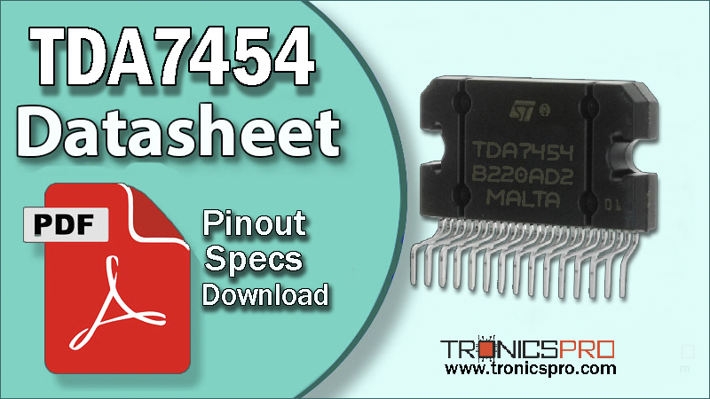
The TDA7454 is a high-efficiency 4 × 35W quad bridge audio amplifier IC designed specifically for car radio and automotive sound systems. Built using advanced BCD technology, it delivers clean, powerful audio output with low distortion and high signal stability. The IC integrates built-in protection circuitry, efficient power handling, and robust thermal characteristics, making it suitable for demanding automotive environments.
Pin Configuration / Pinout of TDA7454 Power Amplifier IC
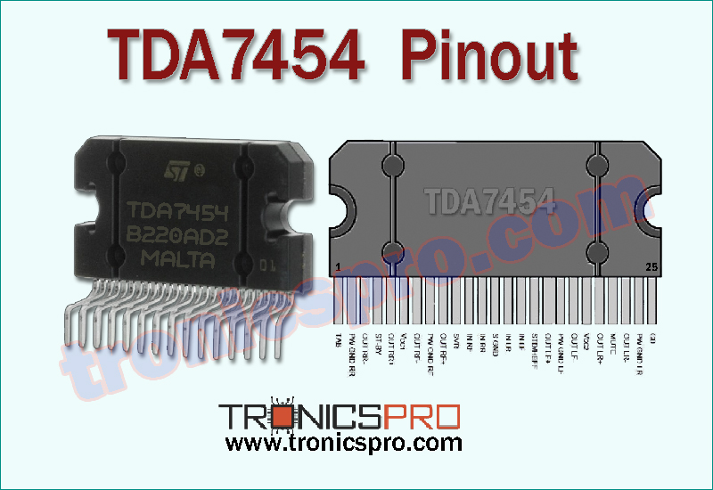
Understanding the TDA7454 Pinout Configuration
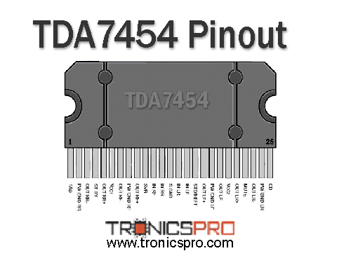
The TDA7454 pinout includes four bridge-tied load outputs, audio inputs for each channel, power supply pins, ground terminals, and additional control pins for enabling, muting, or diagnostic functions depending on application design. Understanding this configuration is essential for proper PCB layout, heat management, and ensuring stable quad-channel audio performance.
| Pin# | Pin Name |
|---|---|
| 1 | TAB |
| 2 | PW GND RR |
| 3 | OUT RR- |
| 4 | ST-BY |
| 5 | OUT RR+ |
| 6 | VCC1 |
| 7 | OUT RF- |
| 8 | PW GND RF |
| 9 | OUT RF+ |
| 10 | SVR |
| 11 | IN RF |
| 12 | IN RR |
| 13 | S GND |
| 14 | IN LR |
| 15 | IN LF |
| 16 | STD/HEFF |
| 17 | OUT LF+ |
| 18 | PW GND LF |
| 19 | OUT LF- |
| 20 | VCC2 |
| 21 | OUT LR+ |
| 22 | MUTE |
| 23 | OUT LR- |
| 24 | PW GND LR |
| 25 | CD |
Note: DATASHEET DOWNLOAD button is provided end of this article.
TDA7454 Key Features
- High-efficiency quad bridge architecture
- Four 35W audio output channels
- Low distortion for improved audio clarity
- Built-in thermal shutdown and short-circuit protection
- Automotive-grade electrical performance
- Stable operation across wide supply variations
- Compact solution for car audio head units
TDA7454 Specifications/Characteristics
- Output Power: 4 × 35W (bridge configuration)
- Supply Voltage Range: 18V to 28V
- Total Power Dissipation: 86W
- Storage Temperature Range: –55°C to +150°C
- High-efficiency audio output stage
- Low total harmonic distortion
- Thermal shutdown protection
- Short-circuit and load-dump protection
- Automotive-grade tolerance and stability
Key Applications of TDA7454 Power Amplifier IC
- Car radio audio amplifiers
- Quad-channel automotive speaker systems
- Vehicle multimedia units
- Aftermarket car amplifier modules
- OEM head units and infotainment systems
- High-efficiency low-distortion audio designs
TDA7454 Equivalent ICs / Alternatives
(Verify pin compatibility before using substitutions)
More Circuit Layouts


Working Principle of TDA7454
The TDA7454 works on a quad bridge-tied load (BTL) configuration, where each channel uses a pair of internal power transistors to provide double-ended amplification. This allows higher output power across low-impedance speakers commonly used in car audio systems. The IC amplifies low-level audio inputs, boosts them through its BCD output stage, and ensures safe operation through integrated thermal, overload, and short-circuit protections. Its high-efficiency design results in lower heat dissipation and reduced power losses.
Frequently Asked Questions (FAQ)
Q1: What is the output power of the TDA7454?
It delivers 4 × 35W using a quad bridge configuration.
Q2: Does the IC have protection features?
Yes, it includes thermal shutdown, short-circuit protection, and load-dump resistance.
Q3: Can the TDA7454 be used in 4-speaker car systems?
Yes, it is designed specifically for quad-speaker automotive setups.
Q4: What supply voltage does it require?
It operates between 18V and 28V, ideal for car electrical systems.
Conclusion
The TDA7454 quad bridge car radio amplifier IC offers high efficiency, strong output power, and reliable automotive-grade performance. With its protective features, stable thermal behavior, and clean audio response, it serves as an excellent choice for modern vehicle audio systems. Understanding its pinout, specifications, and working principle ensures successful integration into quad-channel amplifier designs.
Datasheet of TDA7454 Power Amplifier IC
Click the following Button below to download the datasheet of TDA7454 :
More projects, You may like:
- Video Transmitter DIY Homemade FM Radio Transmitter
- Adjustable Power Supply DIY Battery Charger
- 12V-220V 500 Watt inverter DIY Homemade
- MPPT Solar Charge Controller DIY Homemade
- DIY LA4440 bass amplifier homemade
For more project and circuit diagrams, you can go through the Schematics in the main menu where you can find many interesting projects and circuit diagrams like audio amplifier circuits, voltage booster circuit, battery charger circuit and timer circuits etc., which are all beginner circuit projects. Feel free to check them out!
Thank you for visiting the article.
You may also like:
![tda7264 datasheet pinout equivalent specification application]()
TDA7264 Pinout, Equivalent, Application, Datasheet
![tda7269 datasheet pinout equivalent specification application]()
TDA7269 Pinout, Equivalent, Application, Datasheet
![tda7293 datasheet pinout equivalent specification application]()
TDA7293 Pinout, Equivalent, Application, Datasheet
![tda7266 datasheet pinout equivalent specification application]()
TDA7266 Pinout, Equivalent, Application, Datasheet
![tda7265 datasheet pinout equivalent specification application]()
TDA7265 Pinout, Equivalent, Application, Datasheet
![LM317 Voltage Regulator IC Pinout Datasheet]()
LM317 Voltage Regulator IC Pinout Datasheet
![LM324 Quad Op-Amp IC Pinout Datasheet]()
LM324 Quad Op-Amp IC Pinout Datasheet
![lm7815 datasheet pinout equivalent specification application]()
LM7815 Pinout, Equivalent, Application, Datasheet