
The 13.8v power supply Circuit Diagrams shown below are based on a type 723 voltage regulator because it is reliable, widely available and cheaper than many of the latest high-power (>1.5 A) three-terminal voltage regulators.

The 13.8v power supply Circuit Diagrams shown below are based on a type 723 voltage regulator because it is reliable, widely available and cheaper than many of the latest high-power (>1.5 A) three-terminal voltage regulators.

The circuit described offers an alternative to using a series resistor for voltage dropping, utilizing a series capacitor and bridge rectifier. While there are limitations in terms of only utilizing one half-cycle of the mains waveform, the clever use of a zener diode allows for more efficient rectification.

The 3400V High-Voltage Power Supply Circuit Diagram is a simple unregulated power supply that is capable of providing a maximum voltage of 3400 volts and a load current of 1 ampere. This circuit utilizes a step-up transformer with primary ratings of 230 volts and 10 amperes, and a secondary rating of 2500 volts at 1 ampere

Transformerless Symmetrical Power Supply circuit which gives both polarity (positive and negative) zener regulated output voltages

Many hobbyists use an unregulated battery eliminator for their projects, or design a separate regulated power supply for each project. The circuit shown below is useful for those who need a variable and economical battery eliminator.
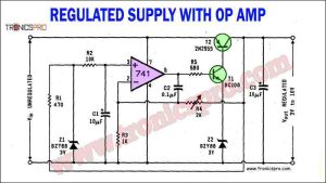
The regulated power supply circuit using the operational amplifier 741, 2n2955, and BC108 transistors provides an effective solution for maintaining stable voltage levels in electronic circuits. By utilizing the operational amplifier as a voltage comparator, the circuit ensures precision in voltage regulation.

In this article, we will discuss a 12V variable power supply circuit diagram using 2N3055, BC547, and BC557 transistors. These transistors, along with a 15V zener diode, play a crucial role in regulating the output voltage and current of the power supply.

The LM317 and LM337 adjustable bipolar voltage regulator circuit provides a reliable and efficient solution for voltage regulation needs, offering stability, accuracy, and versatility in power supply applications.

In this article, we will discuss how to create a Balanced Power Supply Circuit Diagram using the 78L15 and 79L15 ICs, along with the specifications of these ICs and the 1N4002 diodes.

This universal power supply circuit diagram has two output ranges; one from 2.7 V to 12 V, and the other from 10 V to 24 V. The output is short circuit protected. Current limiting is adjustable. These two features are mainly incorporated for preventing accidental damages to the power supply as well as circuits that get power from this supply.

 Variable Power Supply 0-30V_10A Circuit Diagram
 C5200 A1943 TDA2030 Amplifier DIY Homemade
 DIY LA4440 bass amplifier homemade
 2N3055 stereo amplifier homemade bluetooth diy
 DIY bass treble volume homemade Tone Control
 Bass Tone Control Circuit Diagram – TRONICSpro
 500W Power Amplifier Circuit using c5200 a1943
 C5200 A1943 Stereo Amplifier DIY Homemade
 120W Amplifier Circuit Diagram using 2SC5200 & 2SA1943 Apex Kelvin AX14
 120W Power Amplifier Circuit Diagram using 2SC5200 & TL071
 Power Amplifier Circuit with Active Tone Control using 2N3055 Transistors
 500W Power Amplifier Circuit Diagram using 2SC5200 & 2SA1943
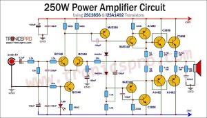 250W Power Amplifier Circuit Diagram using 2SC3856 & 2SA1492
 100W Audio Amplifier Circuit Diagram using TIP3055 & TIP2955
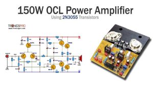 150W OCL Amplifier Circuit Diagram using 2N3055
 100W MOSFET Amplifier Circuit Diagram using 2SK134 & 2SJ49