
Transformerless Symmetrical Power Supply circuit which gives both polarity (positive and negative) zener regulated output voltages

Transformerless Symmetrical Power Supply circuit which gives both polarity (positive and negative) zener regulated output voltages

Many hobbyists use an unregulated battery eliminator for their projects, or design a separate regulated power supply for each project. The circuit shown below is useful for those who need a variable and economical battery eliminator.
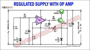
The regulated power supply circuit using the operational amplifier 741, 2n2955, and BC108 transistors provides an effective solution for maintaining stable voltage levels in electronic circuits. By utilizing the operational amplifier as a voltage comparator, the circuit ensures precision in voltage regulation.

The Switchable AC Power Supply circuit diagram offers a practical and flexible solution for obtaining different AC voltages. By harnessing the principles of transformer theory, this circuit allows for the series connection of secondary windings to achieve voltage bucking or boosting.

The circuit diagram of discrete voltage regulator provided is simple and uses a small number of components. The output current capability is determined by the BD680 transistor, but the peak current of 6 A may pose challenges when matching with an integrated voltage regulator.

The 3200V power supply circuit diagram presented here offers an efficient solution for supplying power to a 1kW amplifier in a transmitter. The inclusion of a step/start circuit ensures that the rectifier diodes are not subjected to excessive surge currents during power-on.

In this article, we will discuss a 12V variable power supply circuit diagram using 2N3055, BC547, and BC557 transistors. These transistors, along with a 15V zener diode, play a crucial role in regulating the output voltage and current of the power supply.

The LM317 and LM337 adjustable bipolar voltage regulator circuit provides a reliable and efficient solution for voltage regulation needs, offering stability, accuracy, and versatility in power supply applications.

In this article, we will discuss how to create a Balanced Power Supply Circuit Diagram using the 78L15 and 79L15 ICs, along with the specifications of these ICs and the 1N4002 diodes.

This universal power supply circuit diagram has two output ranges; one from 2.7 V to 12 V, and the other from 10 V to 24 V. The output is short circuit protected. Current limiting is adjustable. These two features are mainly incorporated for preventing accidental damages to the power supply as well as circuits that get power from this supply.

 Variable Power Supply 0-30V_10A Circuit Diagram
 C5200 A1943 TDA2030 Amplifier DIY Homemade
 DIY LA4440 bass amplifier homemade
 2N3055 stereo amplifier homemade bluetooth diy
 Bass Tone Control Circuit Diagram – TRONICSpro
 500W Power Amplifier Circuit using c5200 a1943
 DIY bass treble volume homemade Tone Control
 Subwoofer Amplifier Circuit Diagram using TDA2030
 BD676 Pinout, Equivalent, Applications, Datasheet
 BD675 Pinout, Equivalent, Applications, Datasheet
 BD650 Pinout, Equivalent, Applications, Datasheet
 BD649 Pinout, Equivalent, Applications, Datasheet
 BD648 Pinout, Equivalent, Applications, Datasheet
 BD647 Pinout, Equivalent, Applications, Datasheet
 BD646 Pinout, Equivalent, Applications, Datasheet
 BD645 Pinout, Equivalent, Applications, Datasheet