Introduction
In the field of electronics, the subwoofer is like a blessing for audiophiles. It enhances the low frequency sounds that are responsible for the bass and thump. However, building a subwoofer requires a specific circuit that filters and enhances the low-frequency sound waves. And to achieve that, one of the most popular circuits nowadays is the subwoofer bass booster 4558 IC low pass filter circuit.
The subwoofer bass booster low pass filter circuit is designed using the LM4558 integrated circuit (IC). IC 4558 is a dual operational amplifier that contains two independent op amps. These op amp is used for a wide range of applications such as filters, amplifiers, oscillators, comparators, and more.
Circuit Diagram
of Subwoofer Bass Booster 4558 IC
The circuit diagram for the subwoofer bass booster is shown below, which will guide you to build the project easily.
More Circuit Layouts


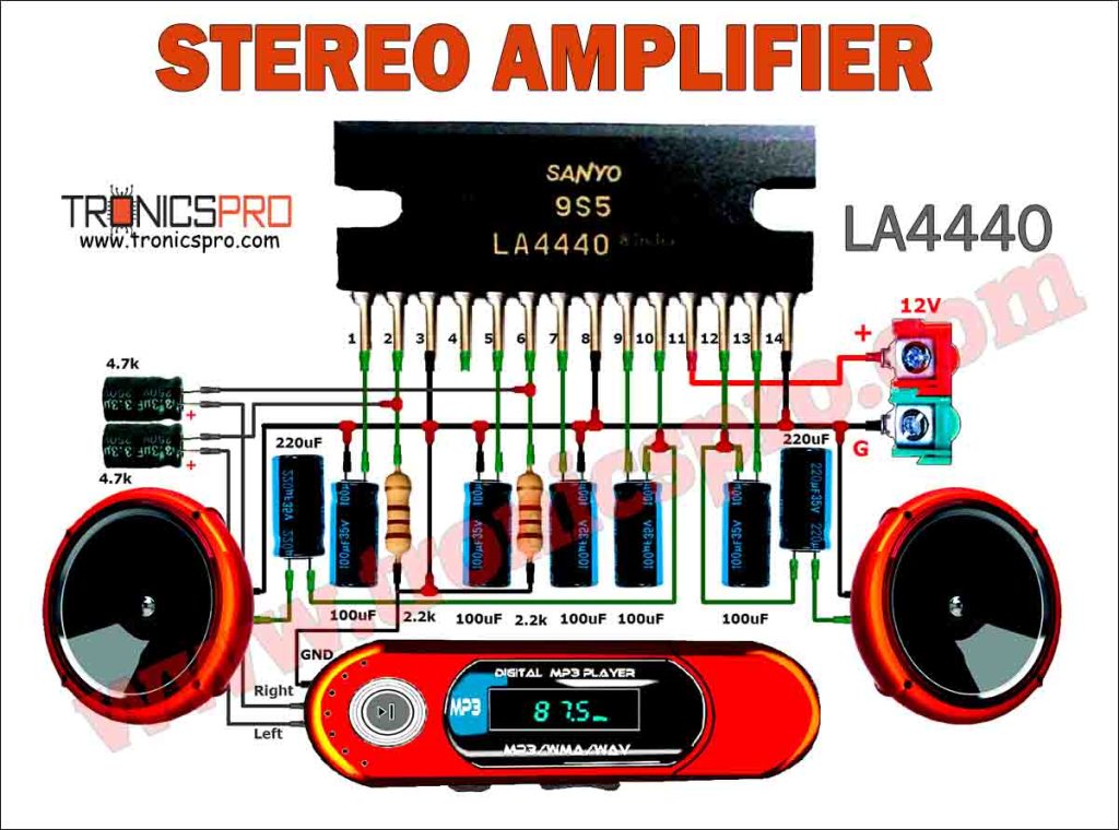
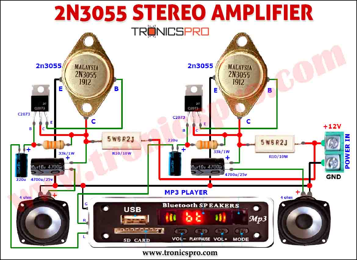
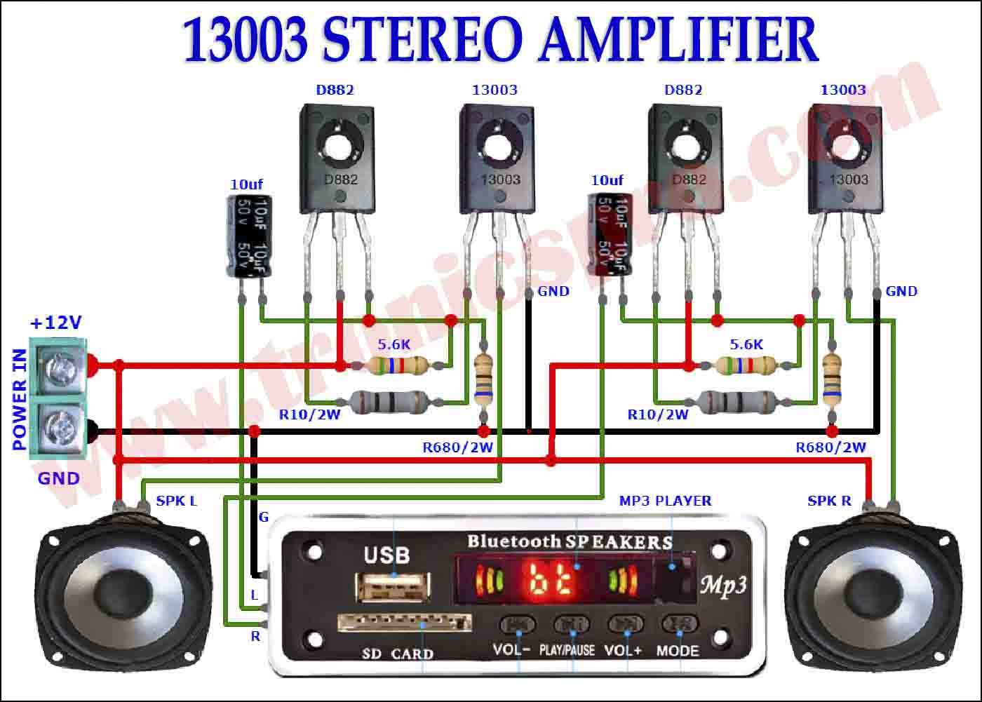

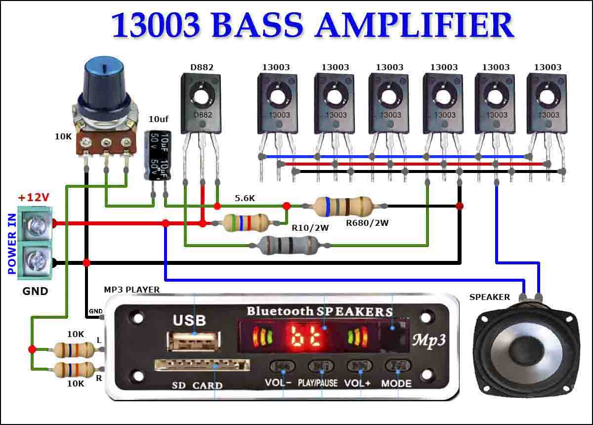
Why use LM4558 ICs?
The LM4558 ICs are preferred for subwoofer circuits because they have a higher gain bandwidth and slew rate which makes them suitable for audio applications. They have a bipolar transistor input stage and are internally frequency compensated for stable operation. The LM4558 IC is designed for low distortion, low noise, and high gain applications.
The 4558 IC subwoofer bass booster low pass filter circuit uses a combination of resistor-capacitor networks, op-amps, and inductors to filter and enhance low-frequency sounds.
The low-pass filter network filters out the high-frequency signals, leaving only the low-frequency sounds. The filtered low-frequency signal is then fed back to the input of the first op-amp through the resistor.
The potentiometer VR1 is used to adjust the gain of the amplifier. It determines the amount of bass boost that is added to the original sound signal.
Components List
of Subwoofer Bass Booster 4558 IC
The main components list used in the circuit is provided below:
- LM4558 IC x 1
- 1uf Capacitor x 1
- 0.1uf (104J) Capacitor x 2
- 100k Potentiometer x 1
- 100k Resister x 1
- 22k Resister x 1
- Power Supply 12v-0v-12v
Conclusion Subwoofer Bass Booster 4558
In conclusion, the subwoofer bass booster 4558 IC low pass filter circuit is an effective way to enhance the low-frequency sounds in audio systems. The LM4558 IC is a suitable choice for audio applications due to their high gain bandwidth and low noise. By building this circuit, audiophiles can enjoy a more enhanced and powerful bass experience.
More projects, You may like:
- Video Transmitter DIY Homemade FM Radio Transmitter
- Adjustable Power Supply DIY Battery Charger
- 12V-220V 500 Watt inverter DIY Homemade
- 12V-220V H-Bridge Inverter DIY Homemade
- MPPT Solar Charge Controller DIY Homemade
- 18650 battery bank free charge protection module
- D718 B688 Bass Amplifier Homemade DIY
- C5200 Bass Amplifier DIY Homemade with Volume
- DIY LA4440 bass amplifier homemade
- C5200 A1943 TDA2030 Amplifier DIY Homemade





I’ve replicated this cicuit, but when i increase bass, sub woofer is vibrating constantly
Hello sir… I have a question… it’s not actually about Jrc4558…. it’s about tda7265…is it amust to use the mica separator between it and heatsink?is it also amust to use the screw with plastic separator?( Stereo amp circuit)