

Introduction
Speech modifier circuit diagrams are helpful tools for engineers when designing speech processing systems. A typical diagram consists of a microphone input, a filter to limit or enhance specific frequency bands in the signal, and an amplifier to adjust the amplitude of the signal. Various analog components like op-amps, capacitors, and resistors are used along with ICs (integrated circuits) such as DSP chips. It is essential to have a well-designed system that produces clear and accurate sound with minimal distortion. By putting together intricate configurations of many different types of components according to one’s needs, circuit diagrams provide an easy way to build reliable speech processors quickly and efficiently.
Circuit Diagram
of Speech Modifier Circuit Diagram

More Circuit Layouts


Working Explanation
of Speech Modifier Circuit Diagram
Nowadays, the speech quality on our telephone systems is generally very good, irrespective of distance. However, there are occasions, for instance, in an amateur stage production, or just for fun, when it is desired to reproduce the speech quality of yesteryear.
The modifier circuit accepts an acoustic (via an electret microphone) or electrical signal. The signals are applied to the circuit inputs via C1‚ and C2, which block any direct voltage. The input cables should be Speech modifier screened.
The signals are brought to (about) the same level by variable potential dividers P1-R1-R4 and P2-R2-R3 and then applied to the base of transistor T1. The level of the combined indicators is raised by this preamplifier.
The preamplifier is followed by an active low-pass filter consisting of T2-T4, C3, C4, R6-Rg, and P4.
Even though strictly talking, p3 serves simply to modify the extent of the signal, its setting does have an effect on the filter function. Note, by the way, that the filter is a rarely encountered current-driven one in which C3 and C4 are the frequency-determining elements. It has a certain similarity with a Wien bridge.
Transistors T3 and T4, in conjunction with resistors R8 and P4, form a variable current sink. The position of P4 determines the slope of the filter characteristic and the degree of overshoot at the cut-off frequency.
The low-pass filter is followed by an integrated amplifier IC1 (741) whose amplification is matched to the input of the electronic circuits connected to the modifier with P5.
The final passive, third-order, high-pass filter is designed to remove frequencies above about 300 Hz.
The resulting output is of a typical nasal character, just as in telephones of the past.
Conclusion
In conclusion, a speech modifier can be an invaluable tool for those who struggle to express themselves clearly. It can help improve pronunciation, grammar, and other aspects of communication by providing real-time feedback as you speak. Speech modifiers can also help you increase your confidence in public speaking and make it easier to build a rapport with your audience. With some practice and dedication, you can see huge improvements in your communication skills.
You may also like:
![2N3055 Power Amplifier Circuit Diagram]()
2N3055 Power Amplifier Circuit Diagram
![Stereo Tone Control Circuit Diagram using NE5532 IC]()
Stereo Tone Control Circuit Diagram using NE5532 IC
![Foldback Current Limiting Circuit Diagram]()
Foldback Current Limiting Circuit Diagram
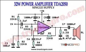
![32W Power Amplifier TDA2050 Single Supply Circuit Diagrm]()
32W Power Amplifier TDA2050 Single Supply
![400W MOSFET Power Amplifier Circuit Diagram using IRFP9240 & IRFP240]()
400W MOSFET Power Amplifier Circuit Diagram using IRFP9240 & IRFP240
![Buck Boost Converter Circuit without Magnetics]()
Buck Boost Converter Circuit without Magnetics
![Bass Amplifier Circuit Diagram using TIP42 & TIP41]()
Bass Amplifier Circuit Diagram using NE5532 OP-Amp
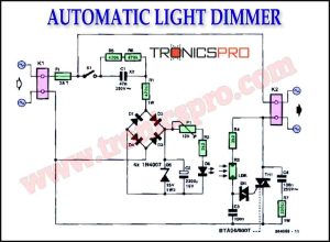
![Automatic Light Dimmer Circuit Diagram]()
Automatic Light Dimmer Circuit Diagram


I like to practice with this type of circuits