
In this video I am going to make a 500 watt inverter using 555 timer IC and a few common components. this inverter is a square wave inverter and it also don’t have feedback to this inverter is suitable for lights fans and other load


In this video I am going to make a 500 watt inverter using 555 timer IC and a few common components. this inverter is a square wave inverter and it also don’t have feedback to this inverter is suitable for lights fans and other load

In this video I have made an universal charger which can charge batteries from 4v upto 18v hope you will enjoy this video. Gerber files circuit diagram is given below please like share and subscribe.

In this video I made a 12vdc to 220vac inverter using very simple method and basic components. I tried to make this Inverter as easy as it can be you can use this inverter for different power ac loads such as power ac lamp or cell phone charger, cell phone charger, small ac fans etc.
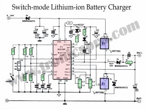
Lithium-ion battery chargers using switch-mode technology is the ideal choice for powering up devices quickly, safely, and efficiently. Unlike standard linear charging methods, switch-mode charging uses a control circuit to more accurately control the amount of current going into the Battery Pack, reducing peak input power and maximizing energy efficiency.

This design is useful in those cases where balanced power lines providing a relatively small output current are needed. The diagram shows a ±15 V supply that can provide a continuous output current of about
25 mA, or 100 mA peak. With other transformers and/or voltage regulators, the supply can be adapted for output voltages of ±5 V, ±9 V, ±12 V, ±15 V, +18V, and ±24 V.
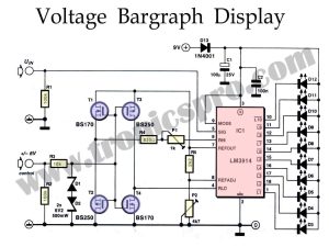
A Voltage Bargraph Display is an invaluable tool for anyone looking to get a detailed, accurate picture of their electrical situation. It’s easy to set up and use, and it can give you a truly comprehensive overview of your system’s voltage usage in real-time.

Time intervals play an important role in electronics and more particularly in test and measurement technology. Normally, a digital circuit is used in which an oscillator provides good resolution and reproducibility. The present circuit is no exception: it consists of a retrig gerable monostable multivibrator (MMV), a Clear circuit, a decimal counter and a BCD-to-decimal counter (BCD-binary coded digit).

In lots of cases, the battery or batteries in digital equipment may be inserted with the wrong polarity. It’s far, therefore, recommended to use polarity protection consisting of proven in the diagrams. It must be mentioned that even though a Schottky diode may be used, this reasons a voltage drop of a few hundred millivolts, which within the case of a 3 v or 1.5 v battery delivery is too much. The safety within the diagrams no longer purpose any discount within the supply voltage.

Over Voltage Protection Circuit (OVPC) is an important safety feature used to protect your electrical system from potentially dangerous voltage surges and spikes. OVPCs are installed in high-stress areas that may be vulnerable to voltage overloads, such as motor control centers, data centers, and more.
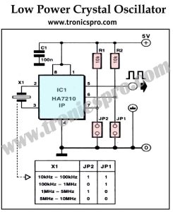
A crystal oscillator is an incredibly useful piece of electronic surveillance equipment that can be used in a variety of applications, such as clocks and timers, radio transmitters and receivers, telecommunication systems, and computers. Its accuracy is unmatched due to its use of quartz crystals whose frequencies can be accurately tuned to a specific resonance frequency.

 Variable Power Supply 0-30V_10A Circuit Diagram
 C5200 A1943 TDA2030 Amplifier DIY Homemade
 DIY LA4440 bass amplifier homemade
 Bass Tone Control Circuit Diagram – TRONICSpro
 2N3055 stereo amplifier homemade bluetooth diy
 500W Power Amplifier Circuit using c5200 a1943
 DIY bass treble volume homemade Tone Control
 Subwoofer Amplifier Circuit Diagram using TDA2030
 KSP92 Pinout, Equivalent Application Datasheet
 KSP44 Pinout, Equivalent Application Datasheet
 MPSA92 Pinout, Equivalent Application Datasheet
 MPSA42 Pinout, Equivalent Application Datasheet
 PN200 Pinout, Equivalent Application Datasheet
 PN100 Pinout, Equivalent Application Datasheet
 MJE802 Pinout, Equivalent Application Datasheet
 MJE800 Pinout, Equivalent Application Datasheet