Introduction
Music is an art form that can be associated with several different mediums. One such medium is the Music Reactive Lights DIY. This unique device is an Arduino Nano powered, PCB board fitted with a music sensor. The device has the ability to sense music and generate a light show relative to the pitch and tempo of the tune being played. It is easy to assemble and disassemble, making it a great DIY project for music and tech enthusiasts alike. The device is suitable for use in various applications, including house parties, concert shows, or even as a centerpiece in a music studio. It is an excellent example of technology and art working hand-in-hand to create something spectacular.
When it comes to music and technology, there are endless possibilities for creativity and innovation. One such example is the Music Reactive Lights DIY project made using an Arduino Nano and a music sensor on a PCB board. This project creates a mesmerizing light show that reacts in real-time to any sound or music in the environment. In this article, we will explore the steps required to build this project, the materials required, and the working mechanism of this innovative product.
Project Video:
Following is the project video of this article which is already uploaded to the YouTube Channel. You can view it here or switch to YouTube Channel for more interesting videos.

Circuit Diagram
of Music Reactive Lights DIY
The circuit diagram consists of an Arduino Nano microcontroller, a music sensor module, several resistors, capacitors, and LEDs connected to a PCB board. The music sensor detects the rhythm and amplitude of the music and sends a signal to the Arduino Nano, which processes the signal and controls the LEDs to react to the music in real time. The resistors and capacitors are used to modify the signal before it is sent to the Arduino Nano. The LEDs are arranged in such a way that they light up in synchronization with the music, thereby creating a music-reactive light show effect.
More Circuit Layouts
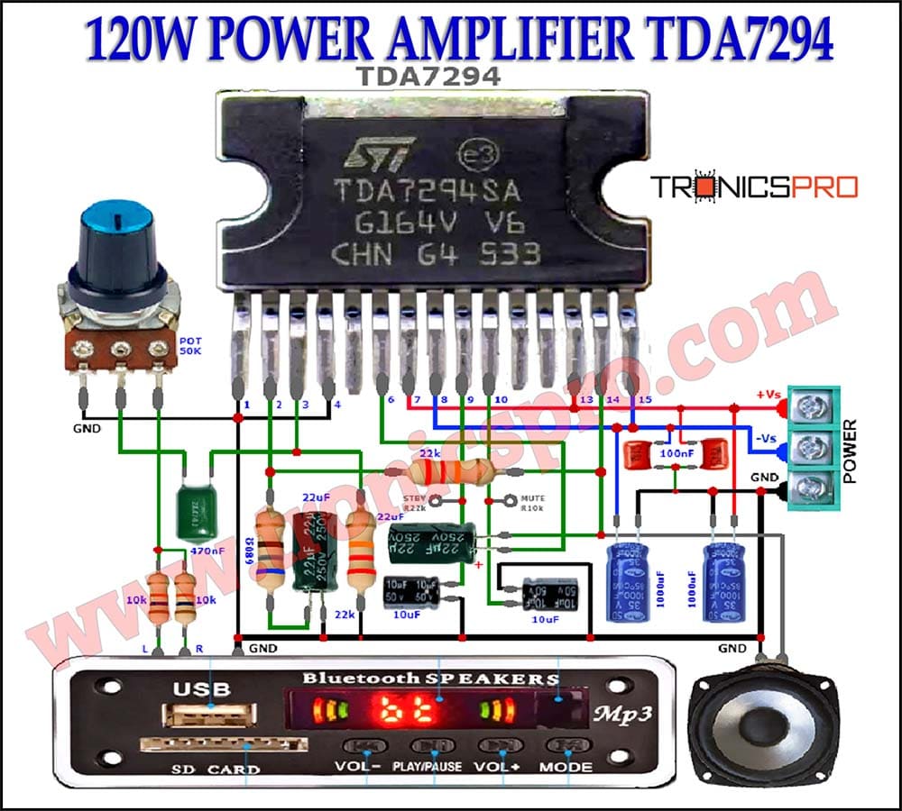
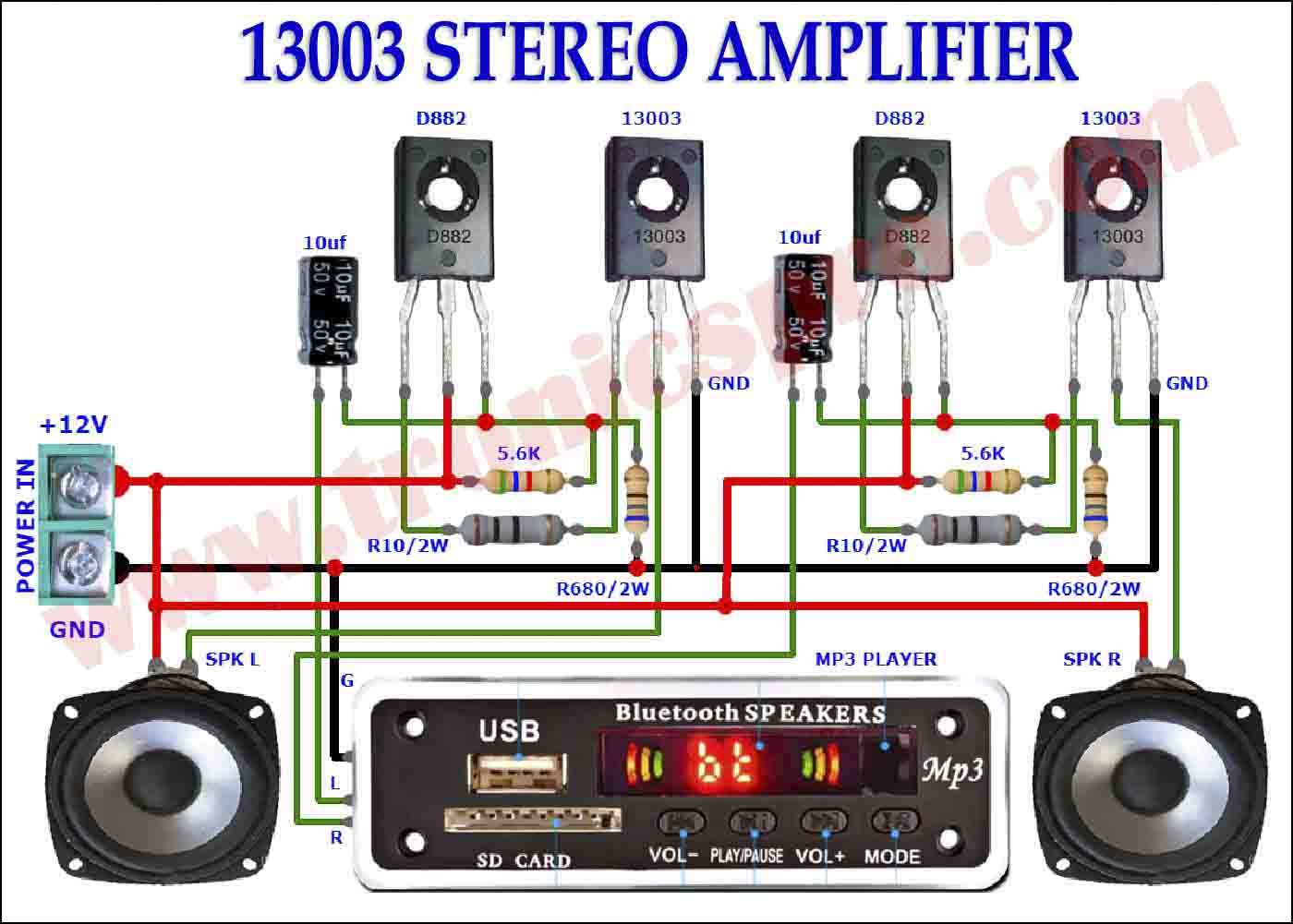

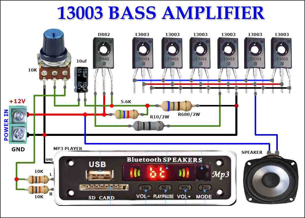


Components List
of Music Reactive Lights DIY
- 1 X Arduino Nano
- 1 X Mic Sensor
- 1 X LEDS or RGB LED strip
- PCB board
- jumper wires
- Soldering iron
- Solder wire
- Power Supply
- Gerber files: https://drive.google.com/file/d/1EGhpiEN7ZfH9fLQUl4_aCnM7aJMn6m9Q/view
- code: Arduino File : https://drive.google.com/file/d/1sScegEyuXNefum0WK44vZ_1VT_Y_orTZ/view
- zip File : https://drive.google.com/file/d/1L8CAekGkm_HfoOuZJLDwHX3qHg7NDM8M/view
- Text File : https://drive.google.com/file/d/1L8CAekGkm_HfoOuZJLDwHX3qHg7NDM8M/view
Working Explanation
of Music Reactive Lights DIY
Step 1: Soldering the Music Sensor Module on PCB
The first step in creating the Music Reactive Lights DIY project is to solder the music sensor module on a PCB board. The music sensor is an essential component of this project as it captures the sound from the environment and converts it into a signal that can be read by the Arduino Nano.
To start, take the PCB board and position the music sensor module on it. Once you have secured the music sensor module in place, use a soldering iron to heat the solder points on the PCB board and attach the music sensor module firmly. Make sure to use caution when soldering, as the soldering iron can reach high temperatures and can cause injury.
Step 2: Connecting the Arduino Nano
Next, connect the Arduino Nano to the PCB board. Take the jumper wires and connect the corresponding pins on the music sensor module to the relevant input pins on the Arduino Nano. The pins to be connected include:
- The output pin of the music sensor module to the analog input pin of the Arduino Nano
- The VCC pin of the music sensor module to the 5V pin on the Arduino Nano
- The GND pin of the music sensor module to the GND pin on the Arduino Nano
Make sure to connect these pins correctly to avoid any damage to the components.
Step 3: Configuring the Arduino Nano
The next step is to configure the Arduino Nano to read the signal from the music sensor module and control the RGB LED strip. This can be done using the Arduino IDE software, which is a free software tool used for programming Arduino boards.
Download the Arduino IDE software from the official website and install it on your computer. Once installed, connect the Arduino Nano to your computer using a USB cable and launch the Arduino IDE software.
In the software, select the board type as “Arduino Nano” and the processor as “ATmega328p (Old Bootloader).” Next, open a new sketch and copy and paste the following code:
This code is used to control the RGB LED strip based on the input signal from the music sensor module. It uses the FastLED library, which is a powerful open-source library used for controlling addressable LED strips.
In this code, the LED_PIN, LED_TYPE, COLOR_ORDER, and NUM_LEDS are defined. The LED_PIN is the pin number to which the RGB LED strip is connected, the LED_TYPE is the type of LED strip used, the COLOR_ORDER is the order in which colors are defined in the RGB LED strip, and the NUM_LEDS is the number of LEDs in the strip.
Inside the setup() function, the FastLED library is initialized with the defined LED type, LED pin, color order, and number of LEDs. The brightness is set to 80% inside this function.
Inside the loop() function, the analog input from the music sensor module is read using the analogRead() function. The signal is then compared to some threshold values to determine the color of the LED strip that should be displayed.
Arduino Code
int a,b,c;
void setup() { Serial.begin(9600);
pinMode(2,OUTPUT);
pinMode(3,OUTPUT);
pinMode(4,OUTPUT);
pinMode(5,OUTPUT);
pinMode(6,OUTPUT);
pinMode(7,OUTPUT);
pinMode(8,OUTPUT);
pinMode(9,OUTPUT);
pinMode(10,OUTPUT);
pinMode(11,OUTPUT);
pinMode(12,OUTPUT);
pinMode(13,OUTPUT);
Serial.begin(9600);
}
void loop() { // read the value from the sensor:
  c++;
a=analogRead(A0);
delay(10);
if(a>50)b=a;

  if(b<90)b=90;
  Serial.println(b);
  if(b>85)digitalWrite(2,HIGH);
  else digitalWrite(2,LOW);
  if(b>170)digitalWrite(3,HIGH);
  else digitalWrite(3,LOW);
  if(b>255)digitalWrite(4,HIGH);
  else digitalWrite(4,LOW);
  if(b>340)digitalWrite(5,HIGH);
  else digitalWrite(5,LOW);
  if(b>425)digitalWrite(6,HIGH);
  else digitalWrite(6,LOW);
  if(b>510)digitalWrite(7,HIGH);
  else digitalWrite(7,LOW);
   if(b>680)digitalWrite(8,HIGH);
  else digitalWrite(8,LOW);
  if(b>765)digitalWrite(9,HIGH);
  else digitalWrite(9,LOW);
  if(b>800)digitalWrite(10,HIGH);
  else digitalWrite(10,LOW);
  if(b>850)digitalWrite(11,HIGH);
  else digitalWrite(11,LOW);
  if(b>935)digitalWrite(12,HIGH);
  else digitalWrite(12,LOW);
  if(b>1020)digitalWrite(13,HIGH);
  else digitalWrite(13,LOW);
   b=b-30;
}
Conclusion
In conclusion, the Music Reactive Lights DIY project made with Arduino Nano and a music sensor on a PCB board is an excellent way to combine music and technology. With this project, you can create a unique and visually stunning light show that reacts to the rhythm and beat of your favorite music. This DIY project is easy to build, even for beginners, and offers endless opportunities for creativity and personalization. By following the instructions and making adjustments, you can customize the light show to match your music tastes, adding an extra layer of fun and entertainment to any party or gathering. Overall, the Music Reactive Lights DIY project is a must-try for all music and tech enthusiasts looking for a fun and exciting project to work on.
More projects, You may like:
- Video Transmitter DIY Homemade FM Radio Transmitter
- Adjustable Power Supply DIY Battery Charger
- 12V-220V 500 Watt inverter DIY Homemade
- 12V-220V H-Bridge Inverter DIY Homemade
- MPPT Solar Charge Controller DIY Homemade
- 18650 battery bank free charge protection module
- D718 B688 Bass Amplifier Homemade DIY
- C5200 Bass Amplifier DIY Homemade with Volume
- DIY LA4440 bass amplifier homemade
- C5200 A1943 TDA2030 Amplifier DIY Homemade


