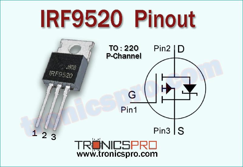
The IRF9520 is a robust P-Channel MOSFET widely used in high-side switching, power control, and voltage-regulation circuits. Its strong voltage capability, dependable thermal performance, and TO-220 package make it highly suitable for medium-power electronic designs. IRF9520 Pinout: (G – D – S)
Introduction to IRF9520 P-Channel MOSFET
The IRF9520 is a power MOSFET designed for applications requiring efficient high-voltage P-Channel operation. Its negative drain-source voltage rating and good current-handling capability make it a reliable component in switching supplies, control stages, motor drivers, and linear regulators. Because of its durable TO-220 package, the IRF9520 offers superior heat dissipation, enabling stable operation under varying load conditions.
IRF9520 P-Channel MOSFET

Pinout of IRF9520
Understanding the IRF9520 Pinout Configuration
The IRF9520 follows a G–D–S (Gate–Drain–Source) pin structure common in TO-220 MOSFETs. The gate terminal controls the device switching, the drain connects to the load, and the source connects toward the supply path. Proper pin identification ensures safe operation and prevents accidental miswiring that could damage the MOSFET or surrounding components.
Pin Configuration of IRF9620 Pinout
| Pin# | Pin Name |
|---|---|
| 1 | Gate |
| 2 | Drain |
| 3 | Source |
Key Features of IRF9520 MOSFET
- High-voltage P-Channel construction
- Reliable performance in switching circuits
- Stable conduction with smooth transitions
- Strong thermal handling capability
- Suitable for medium-power applications
- Durable TO-220 package structure
- Compatible with high-side switching designs
IRF9520 MOSFET Datasheet and Specifications
- Drain-Source Voltage (VDS): –100V
- Gate-Source Voltage (VGS): ±20V
- Continuous Drain Current (ID): –6.8A
- Pulsed Drain Current (IDM): –27A
- Total Power Dissipation (Ptot): 60W
- Drain-Source On-Resistance (RDS(on)): 0.6Ω
- Storage Temperature Range (Tstg): –55°C to 175°C
- Junction Temperature (TJ): 175°C
- Package Type: TO-220
- Pin Order: Gate – Drain – Source
Working Principle of IRF9520 MOSFET
The IRF9520 operates as a P-Channel enhancement MOSFET, meaning it turns ON when the gate is driven negative relative to the source. Once the appropriate negative gate-source voltage is applied, charge carriers create a conductive channel between source and drain. This principle makes the IRF9520 particularly useful in high-side switching, reverse-polarity protection, and power-supply control sections.
More Circuit Layouts


Applications of IRF9520 MOSFET
- High-side load switching
- DC power-supply regulation
- Motor-control driver stages
- Linear and switching regulators
- Battery-powered circuits
- Inverters and converter stages
- General high-voltage power switching
Equivalent and Alternative MOSFETs
Possible equivalents or replacement MOSFETs include:
Always compare RDS(on), voltage ratings, and package type before substitution.
Frequently Asked Questions (FAQ)
Q1: Can IRF9520 be used as a high-side switch?
Yes, its P-Channel structure makes it ideal for high-side switching.
Q2: Does IRF9520 require a heat sink?
In medium to high-power applications, a heat sink is recommended to maintain safe temperatures.
Q3: Can this MOSFET replace IRF9540?
It can in some cases, but always compare current and RDS(on) values before substituting.
Q4: Is IRF9520 suitable for power-supply circuits?
Yes, it is often used in voltage regulation and load-control sections.
Conclusion
The IRF9520 P-Channel MOSFET is a dependable and versatile component for high-voltage switching and power-control applications. With its solid electrical characteristics, strong thermal performance, and TO-220 package durability, it remains a preferred choice for engineers and hobbyists building efficient and reliable electronic systems.
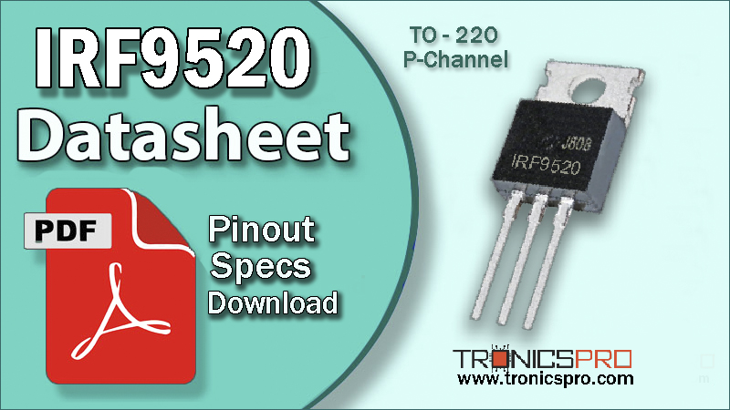
Datasheet & Pinout of IRF9520 P-Channel MOSFET
Click the following Button to download the datasheet of IRF9520 MOSFET :
More projects:
- Video Transmitter DIY Homemade FM Radio Transmitter
- Adjustable Power Supply DIY Battery Charger
- 12V-220V 500 Watt inverter DIY Homemade
- MPPT Solar Charge Controller DIY Homemade
- DIY LA4440 bass amplifier homemade
For more project and circuit diagrams, you can go through the Schematics in the main menu where you can find many interesting projects and circuit diagrams like audio amplifier circuits, voltage booster circuit, battery charger circuit and timer circuits etc., which are all beginner circuit projects. Feel free to check them out!
Thank you for visiting the article.
You may also like:
![irlz24n datasheet pinout equivalent specification application mosfet n-channel]()
IRLZ24N Pinout, Equivalent, Application, Datasheet
![IRF740 datasheet pinout equivalent specification mosfet]()
IRF740 Pinout, Equivalent, Application, Datasheet
![IRFP254 datasheet pinout equivalent specification application mosfet n-channel]()
IRFP254 Pinout, Equivalent, Application, Datasheet
![irfz48 datasheet pinout equivalent specification application mosfet n-channel]()
IRFZ48 Pinout, Equivalent, Application, Datasheet
![IRF644 datasheet pinout equivalent specification application mosfet n-channel]()
IRF644 Pinout, Equivalent, Application, Datasheet
![IRFZ46 datasheet pinout equivalent specification application mosfet n-channel]()
IRFZ46 Pinout, Equivalent, Application, Datasheet
![IRFP150 datasheet pinout equivalent specification application mosfet n-channel]()
IRFP150 Pinout, Equivalent, Application, Datasheet
![IRFP460 datasheet pinout equivalent specification mosfet]()
IRFP460 Pinout, Equivalent, Application, Datasheet