Introduction
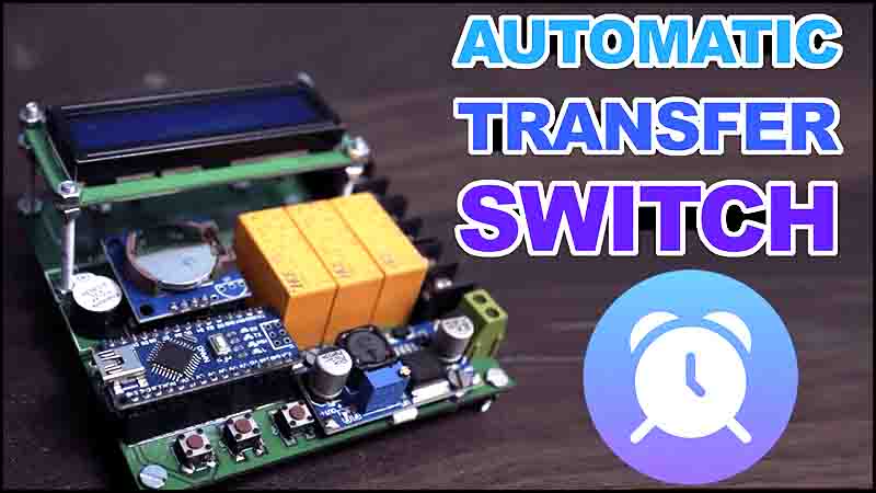
An automatic transfer switch (ATS) is an electrical device that automatically transfers power to the backup generator or utility source when the primary power source fails. This device is used in homes, buildings, and industries to prevent power interruptions during a power outage. An ATS can be controlled manually or automatically. In this article, we will discuss how to make an automatic transfer switch (ATS) using Arduino Nano.
Explanation of How to Make Automatic Transfer Switch
Arduino Nano:
It is a small, compact and low-cost microcontroller board that is based on the ATmega328P microcontroller. It has 14 digital input/output pins, 8 analog pins, and can be powered either through USB or an external power supply. It supports serial communication, SPI and I2C protocols and can be programmed using the Arduino IDE.
RTC Module:
RTC stands for Real Time Clock Module. It is a clock module that keeps track of the current date and time, even when the system is powered off. It generally uses a battery to power up the timing circuit. These modules can be connected to a microcontroller like Arduino to update the time and date and perform other functions.
LM2596 5V Module:
LM2596 is a low dropout voltage regulator that is used to provide a stable output voltage of 5V from an input voltage ranging from 7V to 35V. It can deliver up to 3A current output and is widely used in electronic circuits due to its high efficiency, low cost and reliability.
16×2 LCD Display Module:
It is a 16 character, 2 line alphanumeric LCD display module that can display both text and symbols. It comes with an interface that allows it to be easily connected to microcontrollers like the Arduino. It can display various characters with different fonts and can be used in various applications ranging from simple text messages to more complex data displays.
BC547 Transistor:
BC547 is a general-purpose NPN transistor that is widely used in electronic circuits for switching and amplification purposes. It has a maximum emitter-base voltage of 6V and a collector current of 100mA. It is often used in high-frequency circuits like radio receivers, oscillators, and transmitters due to its low noise and high gain. It is a low-cost transistor that is easily available in the market.

Circuit Diagram of How to Make Automatic Transfer Switch
This project can be designed using a few basic components. The circuit diagram of this project is shown below.
More Circuit Layouts


Components List
of How to Make Automatic Transfer Switch
Following is the list of all components used in this project:
- 1x Arduino Nano
- 1 X RTC Module
- 1X LM2596 5v module
- 1x 16×2 LCD
- 3X BC547 Transistors
- 3X 1N4148 Diodes
- 3x 1K Resistor
- 3x 12V DPDT Relays
- 3x Push Buttons
- 5x 2 Pin Terminal Blocks
- JUMPER WIRES
Building the project of Automatic Transfer Switch
Here are the steps that you can follow to make an automatic transfer switch (ATS) using Arduino Nano:
Step 1: Collect all the components as mentioned in the above provided list.
Step 2: Connect the Arduino Nano to the breadboard using jumper wires or fix in its place on PCB, if it is printed..
Step 3: Connect the input power to the 2-pole toggle switch. The switch will be used to select between primary and secondary source.
Step 4: Connect the output of the switch to the relay module.
Step 5: Connect the relay module to Arduino Nano through the BC547 as per the circuit diagram. The relay module will disconnect the primary source and connect the secondary source when it receives a signal from Arduino Nano.
Step 6: Connect an LED display as shown in the circuit diagram provided above.
Step 7: Connect a 1 kohms resistors between the Pin2 of each BC547 and pins D2, D3, D4 of Arduino Nano.
Step 8: Download the code from above link or write the code to control the ATS.
Step 9: Upload the code to the Arduino Nano. All downloadable links are given above for project files and gerber files.
Step 10: Test the ATS by switching between the primary and secondary source. The LED should light up when the secondary source is connected.
Conclusion of Automatic Transfer Switch
In conclusion, an automatic transfer switch (ATS) is a crucial device to prevent power interruptions during a power outage. We discussed the steps to make an ATS using Arduino Nano. This device can be customized according to the user’s needs. The use of Arduino Nano makes it easy to control and program the ATS. It is cost-effective, easy to use, and reliable. By following the steps mentioned above, you can make your own ATS using Arduino Nano.
More projects, You may like:
- Video Transmitter DIY Homemade FM Radio Transmitter
- Adjustable Power Supply DIY Battery Charger
- 12V-220V 500 Watt inverter DIY Homemade
- 12V-220V H-Bridge Inverter DIY Homemade
- MPPT Solar Charge Controller DIY Homemade
- 18650 battery bank free charge protection module
- D718 B688 Bass Amplifier Homemade DIY
- C5200 Bass Amplifier DIY Homemade with Volume
- DIY LA4440 bass amplifier homemade
- C5200 A1943 TDA2030 Amplifier DIY Homemade


