Introduction
A general-purpose NiCd battery charger is a device that is specifically designed to charge nickel-cadmium batteries. NiCd batteries are widely used in various electronic devices such as radios, toys, and cordless phones. A NiCd battery charger ensures that the battery is charged efficiently and safely, which helps to prolong the battery life and maximize the performance of the electronic device.
The market offers a limited selection of NiCd (nickel-cadmium) battery chargers that can function from a 12-volt car cigarette lighter. This kind of charger could benefit campers and caravanners who lack access to a 230-volt AC mains supply. To cater to the needs of these users, a charger could be created that works from the cigarette lighter while also functioning from a domestic mains supply. Additionally, it would be advantageous if the charger could charge multiple cells simultaneously and automatically switch off once charging is finished.
The charger detailed in this article can charge Type R6 and R14 batteries or cells. A 3-way switch, S1, enables the charger to turn off after various time periods: 2 hours and 30 minutes, 5 hours, or 10 hours. Half the respective periods applies when the switch is in the intermediate position. The charging process is indicated by the activation of light-emitting diode D. Charging may continue after the set period only when the user switches the supply off then on again.
Circuit Diagram
of General-Purpose NiCd Battery Charger

More Circuit Layouts


Working Explanation
of General-Purpose NiCd Battery Charger
Counters IC1 and IC2, specifically Type 4060 and 4020 respectively, determine the time periods. IC1 includes an integrated oscillator whose frequency is established at 932 Hz with the aid of a frequency meter and preset P1. Due to factors such as parasitic components and the values of the components employed, the oscillator operates approximately at 1 kHz. The frequency of the signal at the wiper of P is divided by 2^14, resulting in a signal frequency of 0.056 Hz or one pulse every 17.6 seconds at Q13 of IC. Q13’s signal is linked to the input of IC2’s pin 10. Half the time period occurs at output Q10 when switch S1 is in the intermediate position.
For instance, to obtain a charging period of 2 hours and 30 minutes (9,000 seconds), which equivalent to half a period at output Q9 of IC2, the oscillator period must be 9000×2/16.7×106-1.073 ms, equating to a frequency of 932 Hz as previously noted.
Upon power-on, counter IC2 is the sole element reset; IC1’s likely error of a few seconds is negligible. This arrangement streamlines design. Upon reaching the set period length, and charging is complete, diode D1 extinguishes.
The charging current is sustained by darlington transistor T3, which is a classic current source design with negative feedback. T3 endeavors to retain its emitter potential at 1.3 V, which necessitates zener diode D2. Considering the minimal current (approximately 7 mA) drawn by the diode and its low temperature rise, the thermal stability of this design is acceptable.
Transistor:
Transistor T1 powers the on/off indicator LED and functions solely in the on or off state. Its role is to prevent an overload on the output of counter IC if IC must absorb the entire current (roughly 7 mA) drawn by the diode. Transistor T2 terminates charging by grounding the base of darlington T3 when S’s set time has elapsed.
Diodes:
Diodes D3-D14 are arranged in threes across the terminals of the batteries being charged, with D3-D5 positioned on battery B1, D6-D8 on B2, and so on. D15 inhibits discharged batteries from discharging further after a supply failure. For vehicle use, additional provisions should be implemented to ensure charger operation is not adversely affected by spurious surges on the vehicle power lines.
The battery holder should fit four R6 (AM3; MN1500; SP/HP7; mignon) or R14 (AM2; MN1400; SP/HP11; baby) batteries. The batteries share the same length (approximately 45 mm) but differ in diameter.
When utilized at home, the charger may be powered by a compatible 15 V mains adapter and draws around 150 mA.
Warning: incorrect battery polarity attachment can lead to significant discharge currents and even battery destruction. Ensure that the battery’s correct polarity is verified before inserting it into the holder.
Conclusion
of General-Purpose NiCd Battery Charger
In conclusion, a general-purpose NiCd battery charger is an essential device for anyone who uses electronic devices that require nickel-cadmium batteries. It ensures that the battery is charged safely and efficiently, which can help to extend the lifespan of the battery and maximize the performance of the device. With a NiCd battery charger, users can confidently use their electronic devices without worrying about battery life or performance issues.
More projects, You may like:
- Video Transmitter DIY Homemade FM Radio Transmitter
- Adjustable Power Supply DIY Battery Charger
- 12V-220V 500 Watt inverter DIY Homemade
- 12V-220V H-Bridge Inverter DIY Homemade
- MPPT Solar Charge Controller DIY Homemade
- 18650 battery bank free charge protection module
- D718 B688 Bass Amplifier Homemade DIY
- C5200 Bass Amplifier DIY Homemade with Volume
- DIY LA4440 bass amplifier homemade
- C5200 A1943 TDA2030 Amplifier DIY Homemade

You may also like:
![Amplifier Drive Indicator Circuit Diagram]()
Amplifier Drive Indicator Circuit Diagram
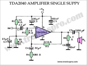
![TDA2040 Power Amplifier 25W Single Supply]()
TDA2040 Power Amplifier 25W Single Supply
![TDA2003 Amplifier Single Supply - Tronicspro]()
TDA2003 Amplifier Single Supply - Tronicspro
![1000W Power Amplifier Circuit using 2SC5200 & 2SA1943]()
1000W Power Amplifier Circuit Diagram using 2SC5200 & 2SA1943
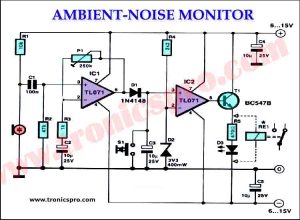
![Ambient Noise Monitor Circuit Diagram]()
Ambient Noise Monitor Circuit Diagram
![13.8v Power Supply Circuit Diagram]()
13.8v Power Supply Circuit Diagram for Mobile Rigs
![2N3055 MJ2955 Class-AB Amplifier Circuit Diagram]()
2N3055 & MJ2955 Class-AB Amplifier Circuit Diagram
![100W Amplifier Circuit using dual 2SC5200]()
100W Amplifier Circuit Diagram using dual 2SC5200