Introduction
The Crystal Frequency Multiplier Upto-160MHz is a device that allows multiplication of the frequency of input signal. It is used in various applications such as communication systems, testing and measurement equipment, and audio processing systems. The ICS501M IC is a high-performance clock multiplier that allows multiplication up to frequencies of 160MHz. It provides low jitter and low phase noise, making it suitable for high-fidelity audio applications. It is also ideal for high-speed digital interfaces.
The fundamental frequency of such a crystal is a third, fifth or seventh of the operating frequency. If, however, an overtone crystal is used in an oscillator designed for operation on the fundamental, it is doubtful whether the wanted frequency will be generated. Sometimes, there are difficulties in most such cases that make it necessary for oscillator circuit to be modified.
Circuit Diagram
of Crystal Frequency Multiplier Upto-160MHz
This amplifier can be designed using a few basic components. The circuit diagram of this project is shown below.

More Circuit Layouts


Components List
of Crystal Frequency Multiplier Upto-160MHz
Capacitors:
- C1, C2 = 33 pF, ceramic
- C3 0.1 uF, ceramic
Integrated circuits:
- IC1 = ICS501M
Miscellaneous:
- Χ1 = crystal 5-20 MHz
- JP1, JP2 = 3-way terminal strip with jumper
Explanation of Crystal Frequency Multiplier Upto-160MHz
One practical solution for such problems is offered by the circuit in the diagram, which enables frequencies up to 160 MHz to be generated with the use of a fundamental-frequency crystal. The output signal is virtually free of any jitter
The circuit makes use of an IC that contains not only an oscillator but also a phase-locked loop (PLL) controlled frequency multiplier. The associated ROM stores nine different multipliers, which may be selected by appropriate placing of the jumpers in JP1 and JP2 as shown in the table. A 0 in the table indicates that the jumper is linked to earth; a 1, that is linked to the +5 V line; and a x that it should be left open.
The circuit may conveniently be built on the printed-circuit board shown, which is not available ready made. About 20 mA current is drawn by the circuit.
Conclusion
The Crystal Frequency Multiplier using the ICS501M IC is a high-performance device that allows multiplication of input signals up to 160MHz. It provides low jitter and low phase noise, making it suitable for a wide range of applications such as communication systems, audio processing systems, and testing and measurement equipment. Its compact size, high reliability and ease of use make it an ideal choice for both professional and hobbyist applications.
More projects, You may like:
- Video Transmitter DIY Homemade FM Radio Transmitter
- Adjustable Power Supply DIY Battery Charger
- 12V-220V 500 Watt inverter DIY Homemade
- 12V-220V H-Bridge Inverter DIY Homemade
- MPPT Solar Charge Controller DIY Homemade
- 18650 battery bank free charge protection module
- D718 B688 Bass Amplifier Homemade DIY
- C5200 Bass Amplifier DIY Homemade with Volume
- DIY LA4440 bass amplifier homemade
- C5200 A1943 TDA2030 Amplifier DIY Homemade

You may also like:
![OCL Amplifier Circuit Diaram using TIP31 & TIP32]()
OCL Amplifier Circuit Diaram using TIP31 & TIP32
![20A Current Monitor Circuit Diagram]()
20A Current Monitor Circuit Diagram
![Stereo Amplifier TDA7297 Dual-Bridge Circuit Diagram]()
Stereo Amplifier TDA7297 Dual-Bridge Circuit
![500W MOSFET Amplifier Circuit Diagram using IRFP448]()
500W MOSFET Amplifier Circuit Diagram using IRFP448 | DIY
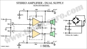
![Stereo Amplifier Dual Supply Circuit Diagram]()
Stereo Amplifier Dual Supply Circuit Diagram
![Simple Variable Power Supply Circuit Diagram]()
Simple Variable Power Supply DIY Circuit Diagram
![Preamplifier Circuit Diagram Low Noise DIY]()
Preamplifier Circuit Diagram Low Noise DIY
![140W Audio Amplifier Circuit using TIP142 TIP147]()
140W Audio Amplifier Circuit Diagram using TIP142 & TIP147