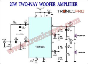
Category: Circuit Diagrams

Selective Door Chime Circuit Diagram

Selective Door Chime Circuit Diagram

The chime is for use in situations where there is bell or chime at the front door as well as at the back door. When loud bells or chimes are used, it may be difficult to determine which one is being rung. This Selective Door Chime Circuit will solve this problem which can produce two or three different sounds. When two of these circuits are built, the one at the front door is set to produce, say, two tones, and the one at the rear door, three tones.

Solar Power Loss Protection Circuit Diagram

Solar Power Loss Protection Circuit Diagram

The combination of OP295 IC and SUB75N MOSFET provides an efficient and reliable solution for solar power loss protection. The OP295 can accurately measure the solar panel voltage and detect any drop in voltage caused by partial shading. The SUB75N then switches the output current of the solar panel to bypass the shaded area and restore power output to its full capacity. With this solution, solar panels can operate efficiently, generate uninterrupted power

Mains Voltage Detector Circuit Diagram

Mains Voltage Detector Circuit Diagram

A Mains Voltage Detector Circuit is an essential electronic circuit in which an essential function is to detect the presence of voltage in the main supply line. The circuit ensures that the presence of electricity is detected before any electrical appliance is operated or any repair work is done. It is a must-have electronic circuit for those who work with electrical appliances or electronic circuits.

150 Watt Lamp Dimmer Circuit Diagram

150 Watt Lamp Dimmer Circuit Diagram

The 150 Watt Lamp Dimmer using 1108APA IC is an efficient and cost-effective way to control the brightness of lamps. The 1108APA IC is a versatile and robust IC that is designed for lighting applications. It uses phase control to dim the lamp, which provides a smooth and gradual transition from full brightness to minimum brightness.

TDA2611 Audio Power Amplifier Circuit Diagram

TDA2611 Audio Power Amplifier Circuit Diagram

The TDA2611 audio power amplifier is an essential component for anyone looking to build a sound system from scratch or improve an existing one. Its robust and compact design makes it an ideal choice for various applications, and its ease of use makes it accessible to a wide range of users. The TDA2611’s reliable and energy-efficient performance, combined with its affordability, has made it a popular choice for sound engineers and DIY enthusiasts all around the world.

Next Page » « Previous Page