Introduction
Bridge Amplifier LM388 Circuit is used to amplify small signals to a higher output voltage, typically using an instrumentation amplifier. A Bridge Amplifier is a parallel configuration of two input stages, where each stage is composed of a CMOS differential amplifier, which is an amplifier that amplifies the difference between the input signals. The circuit is powered by a single power supply and provides balanced input and output.
The bridge amplifier using two LM388 ICs is a simple and cost-effective way to amplify small signals. The LM388 IC is a monolithic power amplifier designed for use in high-performance audio systems. It has a high slew rate, high output current capability, and low distortion. The ICs are configured as instrumentation amplifiers in a bridge configuration, allowing for the common-mode rejection of up to 100 dB.
Circuit Diagram
of Bridge Amplifier LM388 Circuit
The circuit diagram for the bridge amplifier using two LM388 ICs is shown below.

More Circuit Layouts


This circuit is for low-voltage applications requiring high power outputs. Output power levels of 1.0 W into 4 ohms from 6 V and 3.5 V into 8 ohms from 12 V are typical. Coupling capacitors are not necessary since the output dc levels will be within a few tenths of a volt of each other. Where critical matching is required the 500 K potentiometer is added and adjusted for zero dc current flow through the load.
Working Explanation
of Bridge Amplifier LM388 Circuit
The inputs are connected to J1 and J2, which are the inputs and outputs of the bridge amplifier. The 100k potentiometer is used for balance adjustment, which is used to adjust the output to zero when the input signals are equal. The 10k potentiometer is used for volume control. The LM388 ICs are powered by a 15V power supply, which is connected to the power input.
The LM388 ICs are configured as instrumentation amplifiers, which are amplifiers that amplify the difference between the two input signals. The LM388 ICs are designed to provide high gain at low frequencies, which is a requirement for audio applications. The input impedance of the LM388 is 100kohm, which is suitable for low-level input signals.
The LM388 has a high slew rate of 50V/µs, which is the rate at which the output voltage changes in response to changes in the input voltage. This enables the LM388 to respond quickly to the input signals and produce a high-quality output signal. The LM388 also has a high output current capability of 5A, which enables it to drive low-impedance loads.
More Explanations
The bridge configuration of the LM388 ICs provides high common-mode rejection. Which is the ability of the amplifier to reject noise that is common to both input signals. This ensures that only the difference between the two input signals is amplified, resulting in a clean output signal. The common-mode rejection of the LM388 is up to 100dB, which is very high for an audio amplifier.
The 100k potentiometer is used for balance adjustment, which is used to adjust the output to zero when the input signals are equal. This is important for the accurate amplification of small signals, as it ensures that the amplifier is not amplifying any noise or offset voltage. The balance adjustment is performed by adjusting the potentiometer until the output voltage is zero when the input signals are equal.
The 10k potentiometer is used for volume control, which is used to adjust the output level of the amplifier. The volume control is performed by adjusting the potentiometer until the desired output level is achieved. The output level can be adjusted from zero to the maximum level, which is determined by the input signal level and the gain of the amplifier.
Conclusion
In conclusion, the bridge amplifier using two LM388 ICs is a simple and cost-effective way to amplify small signals. The LM388 ICs are configured as instrumentation amplifiers in a bridge configuration, providing high common-mode rejection and accurate amplification of small signals. The use of a 100k potentiometer for balance adjustment. And a 10k potentiometer for volume control makes the circuit flexible and suitable for a wide range of audio applications.
Extra Circuit

More projects, You may like:
- Video Transmitter DIY Homemade FM Radio Transmitter
- Adjustable Power Supply DIY Battery Charger
- 12V-220V 500 Watt inverter DIY Homemade
- 12V-220V H-Bridge Inverter DIY Homemade
- MPPT Solar Charge Controller DIY Homemade
- 18650 battery bank free charge protection module
- D718 B688 Bass Amplifier Homemade DIY
- C5200 Bass Amplifier DIY Homemade with Volume
- DIY LA4440 bass amplifier homemade
- C5200 A1943 TDA2030 Amplifier DIY Homemade

You may also like:
![500W Amplifier Circuit Diagram using 2SC2922 & 2SA1216]()
500W Amplifier Circuit Diagram using 2SC2922 & 2SA1216
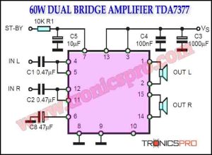
![60W Double-Bridge Stereo Amplifier using TDA7377]()
60W Double-Bridge Stereo Amplifier using TDA7377
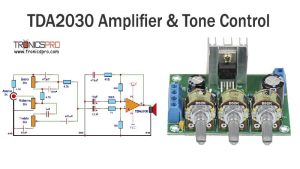
![TDA2030 Amplifier with Tone Control Circuit Diagram]()
TDA2030 Amplifier with Tone Control Circuit Diagram
![Polarity Reverser Circuit Diagram]()
Polarity Reverser Circuit Diagram - TRONICSpro
![30W MOSFET Amplifier Circuit Diagram]()
30W MOSFET Amplifier Circuit Diagram DIY
![TDA2050 Subwoofer Amplifier Circuit Diagram using JRC4558]()
TDA2050 Subwoofer Amplifier Circuit Diagram using JRC4558 IC
![Subwoofer Crossover Circuit Diagram]()
Subwoofer Crossover Circuit Diagram
![500W MOSFET Amplifier Circuit Diagram using IRFP448]()
500W MOSFET Amplifier Circuit Diagram using IRFP448 | DIY