Introduction
Circuit Diagram of Bridge Amplifier LM377 Circuit :
A bridge amplifier is an essential component in many electronic devices, designed to amplify differential signals. In electronic circuits, differential signals refer to the difference between two voltage inputs inducing electrical signals. An amplifier circuit can amplify the difference between these inputs, providing a signal in output proportional to the difference between the inputs. This article will focus specifically on the use of LM377 ICs, a component widely used for its capability to amplify signals.
What is an LM377 IC?
The LM377 is a power amplifier that provides a high output current from a single power supply. Featuring a robust and highly stable internal power-stage design, this IC is capable of producing 1 A peak current (continuous RMS current of 0.4 A) with a load in the range of 4 Ω to 16 Ω. It also comes with features such as thermal shutdown, protection against output short-circuits, and gain control.
What is a Bridge Amplifier?
A bridge amplifier is an essential component in many electronic devices designed to amplify differential signals. It is often used in applications where the input signals have a common mode voltage, which is the voltage at each of the non-inverting and inverting inputs. It serves the purpose of amplifying the difference between two voltage inputs while rejecting the common-mode voltage.
Circuit Diagram
of Power Amplifier MC1538R Circuit
The circuitry of a Bridge Amplifier using LM377 ICs
A bridge amplifier circuit with LM377 ICs is a differential amplifier configuration that uses four resistors and two LM377 power amplifier ICs to form a bridge network. The configuration amplifies the difference between two input signals (Vin1 and Vin2), while rejecting any common-mode signal.

More Circuit Layouts


Working Explanation
of Power Amplifier MC1538R Circuit
To build the circuit, the resistors R1 and R2 act as voltage dividers, while R3 and R4 serve as feedback resistors. The feedback resistors are used to provide an amplified output with an adjustable gain determined by the ratio of these feedback resistors.
The output of the bridge amplifier is taken from the differential output points Vo1 and Vo2, which correspond to the voltage difference between the two inputs. The condition for the differential output voltage Vo is given by the following formula:
Vo = (Vin1 – Vin2) x Av
where Av is the voltage gain of the amplifier.
Design Considerations:
When designing an LM377 bridge amplifier, several things have to be considered:
The required gain and output power: The LM377 can deliver high output power ranging from 3 watts to 12 watts with various amplifier configurations, depending on the desired gain.
The input impedance: The input impedance of the amplifier can be optimized for better detection and noise reduction.
The gain-bandwidth product: The gain-bandwidth product (GBW) determines the bandwidth of the amplifier, which is crucial in applications where high-frequency signal amplifications are required.
The feedback topology: The topology of the feedback circuitry affects the stability and accuracy of the amplifier.
Conclusion
The bridge amplifier using LM377 ICs is an essential component used in many electronic devices for signal amplification. The amplifier configuration amplifies the difference between two input signals while rejecting any common-mode voltage. The circuitry requires four resistors and two LM377 power amplifier ICs to form the bridge network. The gain of the amplifier can be adjusted by the ratio of the feedback resistors, and its output can range from 3 watts to 12 watts, depending on the configuration. Several design considerations, such as the input impedance, gain-bandwidth product, and feedback topology, must be considered when designing an LM377 bridge amplifier to ensure optimal performance.
More projects, You may like:
- Video Transmitter DIY Homemade FM Radio Transmitter
- Adjustable Power Supply DIY Battery Charger
- 12V-220V 500 Watt inverter DIY Homemade
- 12V-220V H-Bridge Inverter DIY Homemade
- MPPT Solar Charge Controller DIY Homemade
- 18650 battery bank free charge protection module
- D718 B688 Bass Amplifier Homemade DIY
- C5200 Bass Amplifier DIY Homemade with Volume
- DIY LA4440 bass amplifier homemade
- C5200 A1943 TDA2030 Amplifier DIY Homemade

You may also like:
![Audio Mixer Preamplifier with Tone Control Circuit]()
Audio Mixer Preamplifier with Tone Control Circuit
![30W Bridge Amplifier TDA7256 Circuit Diagram]()
30W Bridge Amplifier TDA7256 Circuit Diagram
![Bass Amplifier Circuit using 2SC5200 & TDA2030]()
Bass Amplifier Circuit Diagram using 2SC5200 & TDA2030
![Bridge Audio Power Amplifier Circuit Diagram]()
Bridge Audio Power Amplifier Circuit Diagram
![100W Audio Amplifier Circuit Diagram using TIP3055 & TIP2955]()
100W Audio Amplifier Circuit Diagram using TIP3055 & TIP2955
![200W 4-Channel TDA7560 Amplifier Circuit Diagram]()
200W 4-Channel TDA7560 Amplifier Circuit
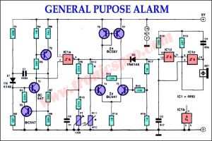
![General Purpose Alarm Circuit Diagram]()
General Purpose Alarm Circuit Diagram
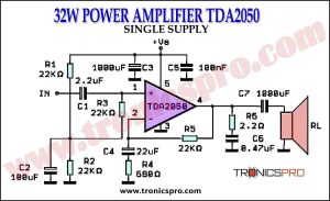
![32W Power Amplifier TDA2050 Single Supply Circuit Diagrm]()
32W Power Amplifier TDA2050 Single Supply