The BC142 is a high-voltage, medium-power NPN transistor widely used in audio drivers, switching supplies, and signal control systems. In this article, we explain the device’s working, features, full electrical specifications, and the BC142 pinout, enabling you to choose and use it effectively in various designs. We also include applications, equivalents, and FAQs for complete understanding.

Introduction
The BC142 transistor is designed for medium-power electronic applications requiring stable gain, voltage handling, and good thermal endurance. Its robust design and ability to manage up to 1A continuous current make it suitable for driver stages, small audio amplifiers, and general-purpose power switching. Engineers prefer the BC142 due to its reliability and broad operating temperature capability.

Pin Configuration / Pinout of BC142 Transistor

Understanding the BC142 Pinout Configuration
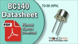
The BC142 comes in a TO-39 package, allowing efficient heat dissipation during medium-power operations. With the flat face toward you and the leads pointing downward, the pinout is:
| Pin# | Pin Name |
|---|---|
| 1 | Emitter |
| 2 | Base |
| 3 | Collector |
This simple arrangement helps in easy PCB integration and ensures proper thermal flow.
Note: DATASHEET DOWNLOAD button is provided end of this article.
BC142 Key Features
- Medium-power NPN configuration
- High voltage tolerance suitable for robust circuits
- Reliable gain stability under varying loads
- Good thermal capability for high-temperature environments
- Suitable for audio, switching, and driver circuits
- Strong mechanical and thermal structure (TO-39 package)
BC142 Specifications/Characteristics
- Collector-Emitter Voltage (Vceo): 60V
- Collector-Base Voltage (Vcbo): 80V
- Emitter-Base Voltage (Vebo): 5V
- Collector Current (Ic): 1A
- Maximum Peak Collector Current (Icm): 1.5A
- Total Power Dissipation (Ptot): 3.6W
- Junction Temperature (Tj): 200°C
- Storage Temperature (Tstg): −55°C to 200°C
- DC Current Gain (hFE): 100–250
- Transition Frequency (fT): 50MHz
Key Applications of BC142 Transistor
- Audio amplifier driver stages
- Medium-power switching circuits
- Relay, motor, and solenoid driving
- Signal control and processing systems
- Power regulators and converter circuits
- General-purpose hobby and educational electronics
BC142 Equivalent / Alternatives
(Verify pin compatibility before using substitutions)
Equivalent Transistors: BC140, BC141
Alternatives: BD135, BD139, 2N2219A (requires circuit adjustments)
More Circuit Layouts


Working Principle of BC142
The BC142 operates as an NPN bipolar transistor where a small base current controls a larger flow between the collector and emitter. Its ability to handle medium currents and high voltages makes it suitable for both linear amplification and power switching. Due to its stable gain and rugged construction, the BC142 performs well even under high thermal stress and demanding load conditions.
Frequently Asked Questions (FAQ)
Q1: Is BC142 good for audio amplification?
Yes, it is widely used in driver and pre-driver stages of audio circuits.
Q2: What package does BC142 use?
It uses the TO-39 package, designed for medium-power dissipation.
Q3: Can BC142 replace BD139?
In many cases yes, but BD139 has a higher power rating, so check circuit requirements.
Q4: What is the maximum operating temperature?
Up to 200°C junction temperature.
Conclusion
The BC142 is a versatile medium-power NPN transistor offering high voltage tolerance, stable gain, and excellent thermal endurance. Its reliable performance makes it ideal for audio, driver, and switching applications. With a rugged TO-39 package and broad operating limits, BC142 remains a dependable choice for both hobbyists and professional circuit designers.
Datasheet of BC142 Transistor
Click the following Button below to download the datasheet of BC142 :
More projects, You may like:
- Video Transmitter DIY Homemade FM Radio Transmitter
- Adjustable Power Supply DIY Battery Charger
- 12V-220V 500 Watt inverter DIY Homemade
- MPPT Solar Charge Controller DIY Homemade
- DIY LA4440 bass amplifier homemade
For more project and circuit diagrams, you can go through the Schematics in the main menu where you can find many interesting projects and circuit diagrams like audio amplifier circuits, voltage booster circuit, battery charger circuit and timer circuits etc., which are all beginner circuit projects. Feel free to check them out!
Thank you for visiting the article.
You may also like:
![2SA1015 PNP Transistor Datasheet Pinout]()
2SA1015 PNP Transistor Datasheet Pinout
![2n3903 datasheet pinout]()
2N3903 Pinout, Equivalent, Application, Datasheet
![2n4037 datasheet pinout]()
2N4037 Pinout, Equivalent, Application, Datasheet
![mje15028 datasheet pinout]()
MJE15028 Pinout Equivalent Application Datasheet
![TIP50 NPN Transistor Datasheet Pinout]()
TIP50 High Power NPN Transistor Datasheet
![2n6100 datasheet pinout equivalent specification]()
2N6100 Pinout, Equivalent, Application, Datasheet
![BD533 NPN Transistor Datasheet]()
BD533 NPN Transistor Pinout Datasheet
![MJ15004 datasheet pinout]()
MJ15004 Pinout Equivalent Applications, Datasheet