The BC141 is a medium-power NPN bipolar junction transistor widely used in driver stages, low-power audio amplifiers, and switching circuits. This article explains its working principle, features, electrical characteristics, and the BC141 pinout, helping engineers and hobbyists integrate it confidently into various analog and power-control designs. We also include datasheet specifications, applications, and suitable equivalents for easy selection.
Introduction
The BC141 is a durable NPN transistor designed for medium-power handling where higher voltage and improved current capability are required. Its stable gain, strong thermal endurance, and reliable switching characteristics make it suitable for numerous audio, amplification, and general-purpose power circuits. The BC141 provides a balance of performance and ruggedness for both industrial and educational use.

Pin Configuration / Pinout of BC141 Transistor
Understanding the BC141 Pinout Configuration
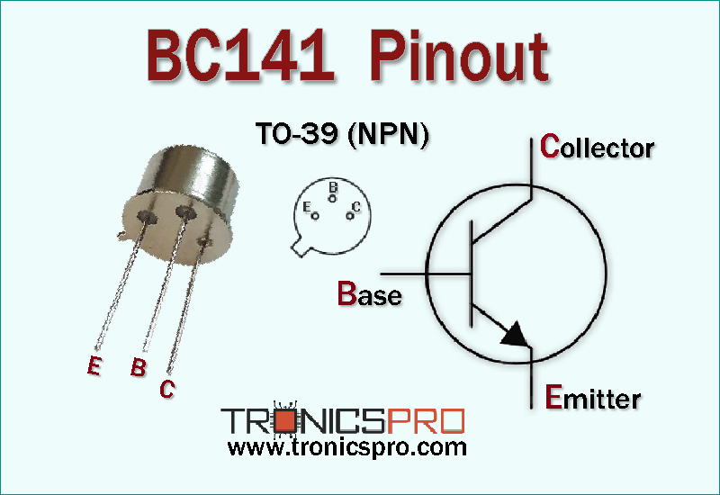
The BC141 transistor comes in a TO-39 package designed for effective heat dissipation. With the flat side facing toward you and leads pointing downward, the pinout is:
| Pin# | Pin Name |
|---|---|
| 1 | Emitter |
| 2 | Base |
| 3 | Collector |
This layout supports easy PCB mounting and efficient thermal performance in medium-power circuit designs.
Note: DATASHEET DOWNLOAD button is provided end of this article.
BC141 Key Features
- Medium-power NPN configuration suitable for drivers
- High voltage tolerance for robust circuit operation
- Reliable gain stability for linear applications
- Rugged TO-39 package for better heat dissipation
- Ideal for audio and switching applications
- Wide operating temperature range for harsh conditions
BC141 Specifications/Characteristics
- Collector-Emitter Voltage (Vceo): 60V
- Collector-Base Voltage (Vcbo): 100V
- Emitter-Base Voltage (Vebo): 7V
- Collector Current (Ic): 1A
- Maximum Peak Collector Current (Icm): 1.5A
- Total Power Dissipation (Ptot): 3.7W
- Junction Temperature (Tj): 175°C
- Storage Temperature Range (Tstg): −65°C to 150°C
- DC Current Gain (hFE): 100–250
- Transition Frequency (fT): 50MHz
Key Applications of BC141 Transistor
- Audio amplifier driver and pre-driver stages
- Medium-power switching circuits
- Relay and motor driver interfaces
- Signal processing and control circuits
- Voltage regulation and power control
- Hobby and educational electronics
BC141 Equivalent / Alternatives
(Verify pin compatibility before using substitutions)
Equivalent Transistors: BC140, BC142
Alternatives: BD139, BD135, 2N2219A (adjustments required)
More Circuit Layouts


Working Principle of BC141
The BC141 works as a standard NPN transistor where applying a small current to the base controls a larger current between the collector and emitter. Its medium-power capability allows it to operate effectively in both linear amplification and switching modes. The high voltage rating and rugged design make it ideal for circuits requiring consistent performance under thermal and electrical stress.
Frequently Asked Questions (FAQ)
Q1: What is the main use of the BC141 transistor?
It is mainly used for medium-power amplification and switching applications.
Q2: Is the BC141 suitable for audio circuits?
Yes, it is commonly used in audio driver and pre-driver stages.
Q3: What package does BC141 use?
It comes in the TO-39 package for better heat dissipation.
Q4: What can replace BC141?
BC140, BC142, BD139, and BD135 are suitable replacements depending on circuit needs.
Conclusion
The BC141 is a reliable and versatile NPN transistor designed for medium-power applications, offering excellent electrical performance, thermal stability, and strong gain characteristics. Its rugged structure and wide application range make it a preferred choice for both professional engineers and hobbyists working on audio, driver, and switching circuits.
Datasheet of BC141 Transistor
Click the following Button below to download the datasheet of BC141 :
More projects, You may like:
- Video Transmitter DIY Homemade FM Radio Transmitter
- Adjustable Power Supply DIY Battery Charger
- 12V-220V 500 Watt inverter DIY Homemade
- MPPT Solar Charge Controller DIY Homemade
- DIY LA4440 bass amplifier homemade
For more project and circuit diagrams, you can go through the Schematics in the main menu where you can find many interesting projects and circuit diagrams like audio amplifier circuits, voltage booster circuit, battery charger circuit and timer circuits etc., which are all beginner circuit projects. Feel free to check them out!
Thank you for visiting the article.
You may also like:
![bc179 datasheet pinout equivalent specification application]()
BC179 Pinout, Equivalent, Application, Datasheet
![BD538 PNP Transistor Datasheet]()
BD538 PNP Transistor Pinout Datasheet
![pn200 datasheet pinout equivalent specification application npn transistor]()
PN200 Pinout, Equivalent Application Datasheet
![2n5088 datasheet pinout]()
2N5088 Pinout, Equivalent, Application, Datasheet
![TIP3055 NPN Transistor Pinout Datasheet]()
TIP3055 NPN Transistor Pinout Datasheet
![BC546 NPN Transistor Datasheet Pinout]()
BC546 NPN Transistor Datasheet
![BD139 NPN Transistor Datasheet Pinout]()
BD139 NPN Transistor Datasheet Pinout
![2n1893 datasheet pinout]()
2N1893 Pinout, Equivalent, Application, Datasheet