Introduction
The Auto Volume Tone Control is intended primarily for insertion between a car radio and its booster. It automatically adapts the volume to the amount of road and engine noise. This is done in four 5 dB steps based on the measured sound pressure in the interior of the car. This means that you can increase the volume up to 20 dB with respect to the set volume level.
Circuit Diagram

More Circuit Layouts


Working Explanation
of Auto Volume Tone Control
Care should, therefore, be taken to ensure that the booster and loudspeakers do not become overloaded. The audio signal is input via K1‚ and K3 and applied to the booster via K2 and K4. The basic level is that registered with the electret microphone MIC 1.
The microphone should not be too sensitive to avoid overdrive and acoustic coupling between it and the loudspeakers. The resistor R1 arranged Its d.c. setting‚ while P1 set its sensitivity.
The output of the microphone is applied to fast op-amp ICâ‚ via the wiper of Pâ‚. The op amp, arranged as a rectifier/amplifier, provides amplification of x45. Its output is averaged by R5-C3 and then applied to comparators IC3a-IC3d. These compare the amplified signal and averaged signal, UAA with the potentials at the junctions of divider R6-R1. Each of these potentials differs by 5 dB from the preceding or next one as the case may be.

The comparators control electronic switches IC5a-IC5d and IC6a-IC6d, which vary in the degree of feedback of IC4g and IC4b on the basis of the control input. For instance, if none of the comparators in IC3 has changed state, IC4a operates as a voltage follower with unity gain. When UAA exceeds the level at junction R6-R7, the gain of IC4a is raised by 5 dB. Whenmwith increasing road and engine noise, it exceeds the level at junction Ro-R10, the switches are all closed so that R13-R16 are in parallel, Whereupon the gain of IC40 is raised by 20 dB. The position of the automatic volume control is indicated by light-emitting diodes D4-D7.
The circuit is powered by the car battery. It is recommended that the battery voltage is well-filtered. The supply lines for the microphone and the voltage divider are held at 8 V by regulator ICâ‚‚. That for IC4 is held at 5.6 V by T1‚-Dg, irrespective of the battery voltage.
The circuit draws a current of 40 mA when the LEDs light. The distortion of 0.0025% is well within the requirements for car hi-fi equipment. The volume control is best built on the printed-circuit board in Figure 2, which is, however, not commercially available, but may be made with the aid of the relevant track layout in Appendix 1.
Project Components
of Auto Volume Tone Control
Resistors:- R1 = 18 k
- R2 = 3.3 k
- R3 = 150 k
- R4 = 5.6 k
- R5 = 470 k
- R6 = 143 k
- R7 = 113 k
- Rg = 200 k
- Rq = 357 k
- R10 = 681 k
- R11, R18, R19, R26 = 100 ohms
- R12, R20 = 47 k
- R13, R21 = 2.15 k, 1%
- R14, R22 = 3.92 k, 1%
- R15, R23 = 7.15 k, 1%
- R16, R24 = 12.7 k, 1%
- R17, R25 = 10 k
- R27-R30 = 3.9 k
- P1 = 100 k preset
Capacitors: - C1‚ = 0.15 uf
- C2, C19 = 220 uf, 25 V, radial
- C3 = 1 uf,
- MKT (metalized polyester), pitch 5 mm or 7.5 mm
- C4, C7, C8, C15, C16, C17 = 0.1 uf
- C5 = 4.7 uf, 63 V, radial
- C6 = 100 uf, 25 V, radial
- C9, C11, C12, C14 = 3.3 uf,
- MKT (metalized polyester), pitch 5 mm or 7.5 mm
- C10, C13= 150 pF
- C18 = 1000 uf, 25 V, radial
Semiconductors: - D1‚ = zener, 4.3 V, 500 mW
- D2, D3 = BAT85
- D4-D7= LED, high-efficiency
- D8 = zener, 5.6. V, 500 mW
- T1‚ = BF245A
Integrated circuits: - IC1‚ = OP17
- IC2 = 78L08
- IC3= TL084
- IC4 = TL072
- IC5, IC6 = 4066
Miscellaneous: - K1-K4 = audio socket for board mounting
- MIC1 = electret microphone
You may also like:
![150W Amplifier Circuit using Sanken 2SC2922]()
150W HiFi Amplifier Circuit using Sanken 2SC2922 & 2SA1216
![150W Power Amplifier Circuit using C5200 A1943 Transistors]()
150W Power Amplifier Circuit Diagram C5200 & A1943 DIY
![20 Watt Power Amplifier Circuit Diagram]()
20 Watt Power Amplifier Circuit Diagram
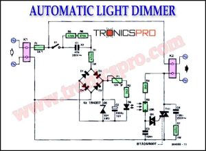
![Automatic Light Dimmer Circuit Diagram]()
Automatic Light Dimmer Circuit Diagram
![Water Leakage Detector Circuit Diagram]()
Water Leakage Detector Circuit Diagram
![Speech modifier circuit diagram]()
Speech Modifier Circuit Diagram
![400W Amplifier Circuit Diagram using 2SC2922 & 2SA1216]()
400W Amplifier Circuit Diagram using 2SC2922 & 2SA1216
![15W Power Amplifier Circuit Diagram]()
15W Power Amplifier Circuit Diagram