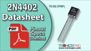
The 2N4918 pinout follows the standard Emitter–Collector–Base (E–C–B) configuration in a TO-126 package, depending on manufacturer variation. The 2N4918 PNP transistor is a medium-power silicon transistor designed for audio amplifier stages, low-frequency drivers, and general-purpose switching circuits. With a collector-emitter voltage of -40V, collector-base voltage of -40V, and a maximum collector current of 1A, the 2N4918 provides excellent balance between power handling and gain stability.
This transistor is known for its robust performance, low distortion, and consistent linear amplification, making it a suitable choice in class AB and class B amplifier designs as well as signal output circuits.

Introduction to 2N4918 PNP Transistor
The 2N4918 transistor is a silicon PNP bipolar junction transistor (BJT) designed for audio and low-frequency power applications. It delivers up to 30 watts of power dissipation, allowing efficient energy transfer in output driver stages, voltage amplifiers, and audio boosters. Its low saturation voltage and thermal stability make it a reliable component in amplifier circuits and audio frequency equipment. The 2N4918 operates with moderate voltage and current levels, making it highly suitable for use in amplifier complementary pairs or push-pull configurations.
2N4918 PNP Transistor

Pinout of 2N4918

Understanding the 2N4918 Pinout Configuration
When facing the flat side or label side of the 2N4918, the pin sequence is Emitter – Collector – Base (E–C–B) from left to right. This configuration simplifies circuit integration, as it matches common layouts for medium-power PNP transistors in audio circuits.
Pin Configuration of 2N4918 Pinout
| Pin# | Pin Name |
|---|---|
| 1 | Emitter |
| 2 | Collector |
| 3 | Base |
Key Features of 2N4918 Transistor
- Designed for medium-power amplification and switching
- Low collector saturation voltage for efficient operation
- Excellent linear gain suitable for audio and driver circuits
- Thermally stable under extended operation
- Reliable silicon construction for durability
- Compact package for easy heat dissipation
2N4918 Transistor Datasheet and Specifications
- Collector–Emitter Voltage (Vce): -40V
- Collector–Base Voltage (Vcb): -40V
- Emitter–Base Voltage (Veb): -5V
- Collector Current (Ic): 1.0A
- Power Dissipation (Pc): 30W
- DC Current Gain (hFE): 30 to 180 (typical)
- Polarity: PNP
- Package Type: TO-126
- Pin Configuration: Emitter–Collector–Base (E–C–B)
Working Principle of 2N4918 PNP Transistor
The 2N4918 operates as a current-controlled device where a small base current regulates a larger collector current. When the base is driven slightly negative relative to the emitter, the transistor allows current to flow from emitter to collector, amplifying the input signal.
Due to its moderate current gain and low saturation voltage, the 2N4918 is ideal for low-frequency power amplifiers, audio drivers, and output stages where signal fidelity is crucial.
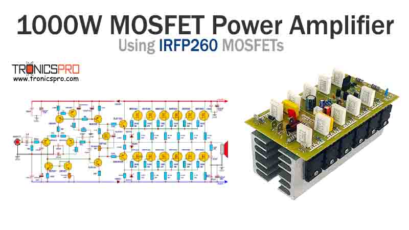
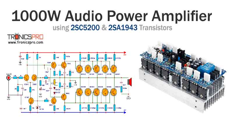
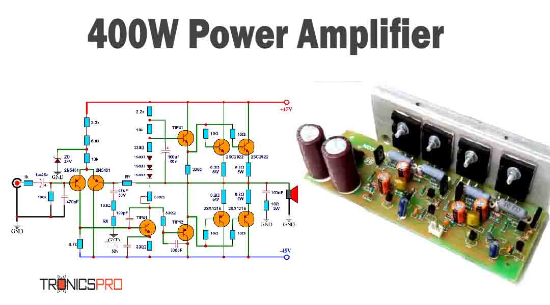
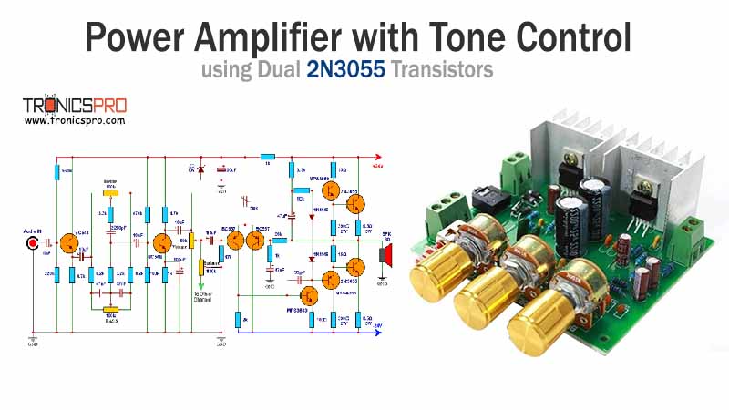
More Circuit Layouts


Typical Applications of 2N4918
- Audio frequency amplifiers and output drivers
- Low-frequency power amplifiers
- Signal switching circuits
- Class B and AB push-pull output stages
- Voltage regulators and motor drivers
- Analog control and instrumentation systems
Equivalent Transistors and Alternatives
- BD242 – Medium-power PNP transistor with similar ratings
- MJ2955 – Power transistor with higher current capability
- TIP32C – PNP transistor alternative for audio amplifiers
- 2N2905A – Lower power replacement for general use
- BD140 – Compact TO-126 equivalent for smaller circuits
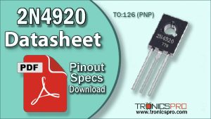
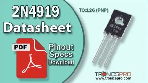
Comparison Summary – 2N4918 vs 2N4919 vs 2N4920
The 2N4918, 2N4919, and 2N4920 transistors belong to the same silicon PNP transistor family, each differing mainly in voltage ratings.
While 2N4918 is rated at -40V, the 2N4919 offers -60V, and the 2N4920 is rated at -80V, providing extended voltage tolerance for higher supply circuits.
In terms of current and power handling, all three share a maximum collector current of 1A and power dissipation of around 30W, maintaining similar thermal and gain characteristics.
Designers often select among these three models based on voltage requirements, as their amplification performance and pin configuration remain nearly identical.
Thus, 2N4918 is suitable for low to moderate voltage amplifiers, 2N4919 for mid-voltage audio drivers, and 2N4920 for higher-voltage amplifier or switching circuits where reliability at elevated voltages is critical.
Frequently Asked Questions (FAQ)
What is the maximum collector current of 2N4918?
It can handle a collector current of up to 1.0A continuously.
What is the voltage rating of 2N4918?
The transistor supports -40V collector-emitter and -40V collector-base voltage.
What is the 2N4918 pin configuration?
The 2N4918 pinout is Emitter–Collector–Base (E–C–B) from left to right when viewed from the front.
What is the power dissipation of 2N4918?
The maximum power dissipation is 30W, making it suitable for small to medium power applications.
What are the differences between 2N4918, 2N4919, and 2N4920?
They mainly differ in voltage ratings: -40V for 2N4918, -60V for 2N4919, and -80V for 2N4920, with similar current and power capabilities.
Conclusion
The 2N4918 PNP transistor is a versatile medium-power device offering excellent linear gain, thermal stability, and low distortion, perfect for audio driver and low-frequency amplifier circuits.
Compared with 2N4919 and 2N4920, it provides the same current and power output but is optimized for lower voltage circuits, ensuring safe and efficient operation.
With reliable performance and ease of replacement, the 2N4918 continues to be a trusted choice for amplifier designers and power circuit engineers.
Datasheet & Pinout of 2N4918 PNP Transistor
Click the following Button to download the datasheet of 2N4918 Transistor :
More projects, You may like:
- Video Transmitter DIY Homemade FM Radio Transmitter
- Adjustable Power Supply DIY Battery Charger
- 12V-220V 500 Watt inverter DIY Homemade
- MPPT Solar Charge Controller DIY Homemade
- DIY LA4440 bass amplifier homemade
For more project and circuit diagrams, you can go through the Schematics in the main menu where you can find many interesting projects and circuit diagrams like audio amplifier circuits, voltage booster circuit, battery charger circuit and timer circuits etc., which are all beginner circuit projects. Feel free to check them out!

Thank you for visiting the article.


