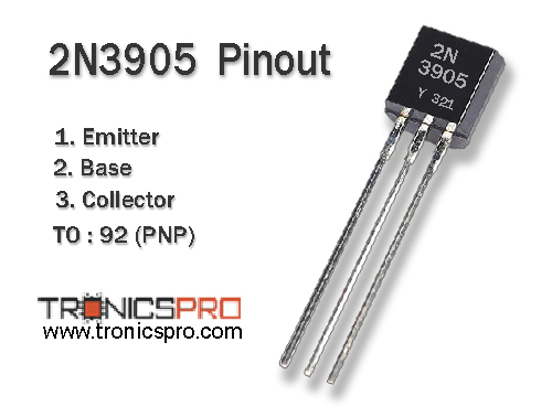
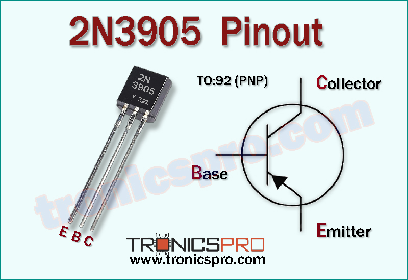
The 2N3905 pinout follows the Emitter–Base–Collector (E–B–C) configuration, which makes it a perfect PNP transistor for switching and amplification in low-power electronic circuits. Known for its fast response, low leakage current, and stable gain, the 2N3905 is widely used in analog signal processing, audio circuits, and general-purpose low-voltage designs.

Introduction to 2N3905 PNP Transistor
The 2N3905 is a PNP silicon bipolar junction transistor (BJT) primarily designed for general-purpose low-power applications. It complements the popular 2N3903 NPN transistor, providing balanced performance for push-pull amplifier stages and signal switching circuits.
With a collector-emitter voltage (Vce) of –40 V, collector-base voltage (Vcb) of –40 V, and a maximum collector current (Ic) of –200 mA, it performs reliably in signal amplifiers, oscillators, and small-load switching. The TO-92 plastic package ensures easy PCB mounting, compactness, and low cost — making it a preferred choice for both professional and educational electronics projects.
2N3905 PNP Transistor
Pinout of 2N3905
Understanding the 2N3905 Pinout Configuration
When viewed from the flat side, the 2N3905 pinout sequence is Emitter–Base–Collector (E–B–C). The emitter is the leftmost lead, followed by the base in the center, and the collector on the right. This standard pin layout simplifies circuit design, especially for breadboards and prototyping.
Pin Configuration of 2N3905 Pinout
| Pin# | Pin Name |
|---|---|
| 1 | Emitter |
| 2 | Base |
| 3 | Collector |
Key Features of 2N3905 Transistor
- Designed for low-power general-purpose PNP applications
- Fast switching speed for analog and digital signals
- Excellent gain stability over temperature variations
- Low collector-emitter saturation voltage
- Suitable for complementary-pair circuits with 2N3903
- Compact and thermally efficient TO-92 package
2N3905 Transistor Datasheet and Specifications
- Collector–Emitter Voltage (Vce): –40 V
- Collector–Base Voltage (Vcb): –40 V
- Emitter–Base Voltage (Veb): –6 V
- Collector Current (Ic): –200 mA
- Total Power Dissipation (Pc): 625 mW
- DC Current Gain (hFE): 70 to 300
- Transition Frequency (fT): 250 MHz (typical)
- Package Type: TO-92
- Polarity Type: PNP
- Pin Configuration: Emitter–Base–Collector (E–B–C)
Working Principle of 2N3905 Transistor
The 2N3905 PNP transistor operates by allowing current to flow from the emitter to the collector when a small negative voltage is applied to the base relative to the emitter. It functions as a current-controlled device, where a tiny base current enables a much larger collector current.
In amplifier configurations, the 2N3905 amplifies weak input signals with minimal distortion, while in switching applications, it toggles between cutoff and saturation states, acting as an efficient low-side or high-side driver for low-power circuits.
More Circuit Layouts


Typical Applications of 2N3905
- Signal and audio amplification stages
- Low-power switching circuits
- Complementary push-pull amplifier configurations
- Sensor and detector circuits
- Logic inverters and small-load drivers
- Educational electronics and experimentation projects
NPN Complementary Transistor
The complementary NPN transistor for the 2N3905 is the 2N3903. These two transistors form a matched complementary pair for Class-B or Class-AB push-pull amplifiers, offering symmetrical drive capability for both positive and negative signal cycles. The pairing ensures improved linearity, efficiency, and signal fidelity in analog circuits.
Equivalent Transistors and Alternatives
- BC557 (low-power PNP with similar ratings)
- 2N3906 (alternate PNP with extended gain)
- 2SA1015 (higher current alternative)
- S8550 (Asian equivalent for small-signal PNP)
- PN2907 (similar package and electrical parameters)
Comparison Summary: 2N3905 vs 2N3904
The 2N3905 (PNP) and 2N3903 (NPN) transistors are complementary devices designed for low-power and signal-level electronic circuits. While both share similar current, voltage, and gain characteristics, they differ in polarity and conduction behavior.
The 2N3905 conducts when the base is negative relative to the emitter, while the 2N3903 requires a positive base bias. Together, they form an ideal pair for push-pull amplifiers, audio circuits, and balanced switching applications, providing stable and efficient bidirectional current control.
Frequently Asked Questions (FAQ)
What is the maximum voltage rating of the 2N3905?
It supports up to –40 V between collector and emitter and –40 V between collector and base.
Can 2N3905 be used for amplification?
Yes, it is widely used for audio and signal amplification due to its low noise and stable gain.
What is the 2N3905 pin configuration?
The 2N3905 pinout is Emitter–Base–Collector (E–B–C) when viewed from the flat side of the TO-92 package.
What is the complementary transistor for 2N3905?
The 2N3903 is the NPN complementary pair for the 2N3905.
Is 2N3905 the same as 2N3906?
Both are PNP transistors, but the 2N3906 typically offers slightly different gain and switching speed characteristics.
Conclusion
The 2N3905 PNP transistor is a compact, low-power component ideal for switching, signal amplification, and complementary pairing with NPN types like 2N3903. Its reliable electrical characteristics, high transition frequency, and stable operation make it an excellent choice for both analog and digital circuits.
Whether used in hobby electronics, small-signal amplifiers, or driver circuits, the 2N3905 ensures dependable performance and versatility in a wide range of low-voltage applications.
Datasheet & Pinout of 2N3905 NPN Transistor
Click the following Button to download the datasheet of 2N3905 Transistor :
More projects, You may like:
- Video Transmitter DIY Homemade FM Radio Transmitter
- Adjustable Power Supply DIY Battery Charger
- 12V-220V 500 Watt inverter DIY Homemade
- MPPT Solar Charge Controller DIY Homemade
- DIY LA4440 bass amplifier homemade
For more project and circuit diagrams, you can go through the Schematics in the main menu where you can find many interesting projects and circuit diagrams like audio amplifier circuits, voltage booster circuit, battery charger circuit and timer circuits etc., which are all beginner circuit projects. Feel free to check them out!
Thank you for visiting the article.
You may also like:
![BD240 PNP Transistor Datasheet]()
BD240 PNP Transistor Pinout Datasheet
![bd710 datasheet pinout]()
BD710 Pinout, Equivalent, Applications, Datasheet
![2SC1943 PNP Transistor Thumbnail]()
2SA1943 PNP Transistor - Datasheet
![MJE13009 Power Transistor Datasheet]()
MJE13009 NPN Power Transistor Datasheet
![2SA1015 PNP Transistor Datasheet Pinout]()
2SA1015 PNP Transistor Datasheet Pinout
![BC546 NPN Transistor Datasheet Pinout]()
BC546 NPN Transistor Datasheet
![TIP120 NPN Transistor Datasheet]()
TIP120 NPN Transistor Pinout Datasheet
![2N3906 PNP Transistor Datasheet Pinout]()
2N3906 PNP Transistor Datasheet & Pinout