Introduction
A power amplifier is an electronic device that amplifies low-level electronic signals into high-level electronic signals for driving loudspeakers. The TDA7294 is a popular power amplifier chip that is widely used in audio amplifiers for its efficiency, simplicity, and ruggedness. In this project, we will design a 120W power amplifier using the TDA7294 IC with a potentiometer and MP3 Bluetooth.
The TDA7294 is a Class AB audio amplifier that can deliver up to 120W of power into an 8 ohm load. It has a high input impedance of 100k ohms, which makes it suitable for use in many audio applications. The TDA7294 also has built-in protection circuits for thermal overheating, short-circuiting, and overloading. This makes it a robust and reliable power amplifier chip for audio applications.
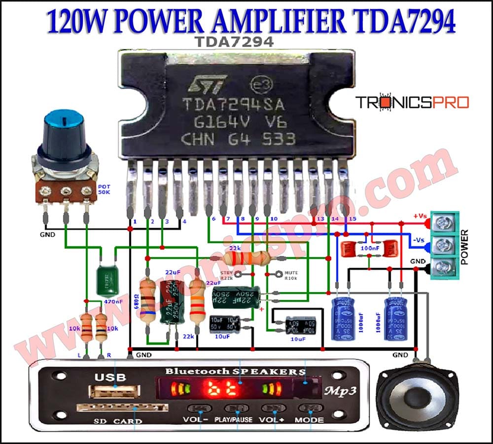
Circuit Diagram
of 120W Power Amplifier TDA7294
This amplifier can be designed using a few basic components. The circuit diagram of this project is shown below.
Components List of 120W Power Amplifier TDA7294
- TDA7294 IC x 1
- 10uF Capacitor x 2
- 22uF Capacitor x 2
- 1000uF Capacitor x 2
- 470nF Capacitor x 1
- 100nF Capacitor x 2
- 10k Resister x 3 (one for MUTE)
- 22k Resister x 3 (one for STBY)
- 50k Potentiometer x 1
- Speaker 4Ω-8Ω
- Power Supply 24V-30V
More Circuit Layouts


TDA7294 Pin Configuration

Project Explanation
In this project, we will use a potentiometer to control the volume of the amplifier. The potentiometer will be connected to the input of the amplifier circuit to adjust the gain of the amplifier. A Bluetooth module will also be integrated into the circuit to allow for wireless streaming of audio from smartphones, tablets, or PCs.
The MP3 Bluetooth module will be connected to the input of the amplifier circuit. The audio signal transmitted from a Bluetooth device will be received by the module and then amplified by the TDA7294. The amplifier circuit will be powered by a 24V DC power supply, which will provide sufficient power to drive the loudspeakers.
The project will be built on a printed circuit board (PCB). The PCB can be designed using any PCB design software, which is a widely used tool for designing electronic circuits. The PCB design will include the TDA7294 IC, the potentiometer, the Bluetooth module, and the other passive components required for the amplifier circuit.
Conclusion of 120W Power Amplifier TDA7294
The TDA7294 is a versatile and reliable power amplifier chip that is widely used in audio amplifiers. With its high input impedance and built-in protection circuits, it is suitable for use in many audio applications. In this project, we have designed a 120W power amplifier using the TDA7294 IC with a potentiometer and MP3 Bluetooth. The potentiometer will be used to control the volume of the amplifier, while the MP3 Bluetooth module will allow for wireless streaming of audio from Bluetooth devices. The amplifier circuit will be built on a PCB and powered by a 24V DC power supply. The project will provide an excellent opportunity to learn about audio amplifier design, PCB design, and electronics. By completing this project, one will have a functional amplifier that can be used to drive loudspeakers and enjoy high-quality audio at home or in a small event setting.
More projects, You may like:
- Video Transmitter DIY Homemade FM Radio Transmitter
- Adjustable Power Supply DIY Battery Charger
- 12V-220V 500 Watt inverter DIY Homemade
- 12V-220V H-Bridge Inverter DIY Homemade
- MPPT Solar Charge Controller DIY Homemade
- 18650 battery bank free charge protection module
- D718 B688 Bass Amplifier Homemade DIY
- C5200 Bass Amplifier DIY Homemade with Volume
- DIY LA4440 bass amplifier homemade
- C5200 A1943 TDA2030 Amplifier DIY Homemade


Please add a pcb tamplet also