Introduction
Audio amplifiers serve as integral components in sound systems, providing the necessary power to drive speakers and deliver high-quality sound output. Among the diverse range of amplifier designs, the 100W Audio Amplifier Circuit Diagram featuring 2N3055, MJ15004 in the output section, along with MPSA06, MPSA56, BD139, and 2N3904 transistors in the driver and preamplifier sections stands out for its reliability and performance.
Specifications of Transistors Used:
2N3055:
Collector-Emitter Voltage (VCEO): 60V
Collector Current (IC): 15A
Power Dissipation (PD): 115W
MJ15004:
Collector-Emitter Voltage (VCEO): 140V
Collector Current (IC): 20A
Power Dissipation (PD): 250W
MPSA06:
Collector-Emitter Voltage (VCEO): 80V
Collector Current (IC): 500mA
Power Dissipation (PD): 625mW
MPSA56:
Collector-Emitter Voltage (VCEO): -80V
Collector Current (IC): -500mA
Power Dissipation (PD): 625mW
BD139:
Collector-Emitter Voltage (VCEO): 80V
Collector Current (IC): 1.5A
Power Dissipation (PD): 8W
2N3904:
Collector-Emitter Voltage (VCEO): 40V
Collector Current (IC): 200mA
Power Dissipation (PD): 625mW
100W Audio Amplifier Circuit Diagram using 2N3055 & MJ15004
This project can be built using a few basic components. The circuit diagram of this project is shown below.
Caution: Website contains information on high voltage circuits. Proceed at your own risk, ensuring proper knowledge and precautionary measures to prevent electric shock or injury.
More Circuit Layouts

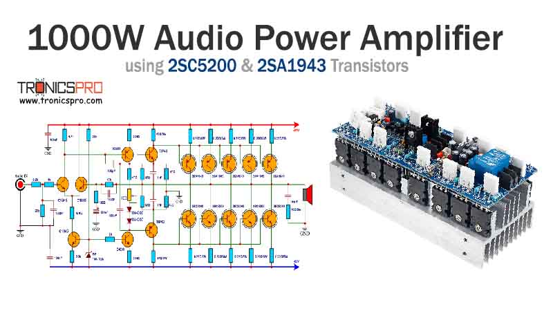
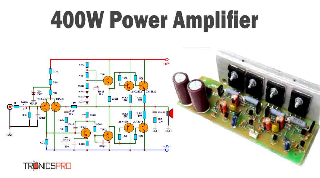
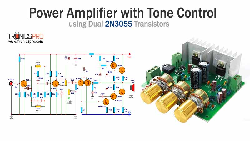




Components List of 100W Audio Amplifier Circuit Diagram using 2N3055 & MJ15004
Following is the list of all components used in this project:
Transistors:
- 2N3055 Transistor x 1
- MJ15004 Transistor x 1
- MPSA06 Transistor x 3
- MPSA56 Transistor x 3
- BD139 Transistor x 1
- 2N3904 Transistor x 2
Resisters:
- 15k Resister x 1
- 560 Resister x 2
- 5.6k Resister x 1
- 12k Resister x 1
- 470 Resister x 1
- 30k Resister x 1
- 1.2k Resister x 4
- 10k Resister x 4
- 10 Resister x 1
- 100 Resister x 5
- 330 Resister x 2
- 0.22 Resister x 2
Capacitors:
- 1uF Capacitor x 1
- 47uF Capacitor x 3
- 47pF Capacitor x 1
- 0.1uF Capacitor x 1
Miscellaneous:
- 1N5239D Zener Diode x 1
- 1N4148 Diode x 2
- 0.53uH Coil x 1
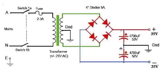
- ±35V Symmetrical Power Supply
Explanation of 100W Audio Amplifier Circuit Diagram using 2N3055 & MJ15004
The essence of this audio amplifier circuit lies in its output stage, where the 2N3055 and MJ15004 transistors operate to deliver robust power to the speakers. These transistors are configured to handle high power loads while maintaining stability and efficiency. Serving as drivers, the MPSA06, MPSA56, BD139, and 2N3904 transistors control the flow of current through the output transistors, ensuring precise amplification of the input signal.
The preamplifier section, comprising MPSA06, MPSA56, BD139, and 2N3904 transistors, amplifies the input signal before it reaches the output stage. This amplification process boosts the signal to a level suitable for driving the output transistors, thereby enhancing overall performance and fidelity.
Conclusion
The 100W Audio Amplifier Circuit Diagram featuring 2N3055, MJ15004 in the output section, and MPSA06, MPSA56, BD139, and 2N3904 transistors in the driver and preamplifier sections presents a reliable solution for amplifying audio signals with clarity and power. By leveraging the capabilities of each component and carefully designing the circuit layout, this amplifier delivers high-fidelity sound reproduction suitable for various audio applications. Understanding the circuit design and component specifications empowers enthusiasts to construct and customize audio amplifiers to meet their specific needs.
More projects, You may like:
- Video Transmitter DIY Homemade FM Radio Transmitter
- Adjustable Power Supply DIY Battery Charger
- 12V-220V 500 Watt inverter DIY Homemade
- MPPT Solar Charge Controller DIY Homemade
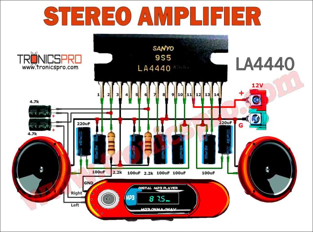
- DIY LA4440 bass amplifier homemade
For more project and circuit diagrams, you can go through the Schematics in the main menu where you can find many interesting projects and circuit diagrams like audio amplifier circuits, voltage booster circuit, battery charger circuit and timer circuits etc., which are all beginner circuit projects. Feel free to check them out!

Thank you for visiting the article.


