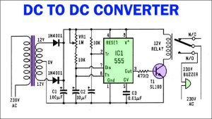
The DC to DC converter circuit employing a 555 Timer IC and an SL100 transistor demonstrates exceptional efficiency and flexibility in voltage conversion. By intelligently utilizing the characteristics of these components, the circuit ensures a regulated and stable power supply, making it suitable for a diverse range of applications.
Tag: boost converter circuit
How to Make DC to DC Boost Converter using UC3843
DC to DC boost converter is a valuable circuit for increasing the output voltage of a power source. By following the guidelines mentioned in this article, you can successfully make a DC to DC boost converter using the UC3843 PWM Controller IC and other components.
How to Make Boost Converter DIY Homemade
By following the step-by-step guide, you can build a boost converter DIY homemade to meet your specific voltage requirements. In this article, we’ve discussed how to make a boost converter using the MC34063 IC.
Mains Frequency Converter Circuit Diagram
The device called the converter changes an unstable voltage frequency from a mains source into a stable one using quartz crystal technology. Additionally, it has the capability to convert the mains frequency to either 100 Hz or 25 Hz from the standard 50 Hz. This Mains Frequency Converter Circuit is beneficial for providing an accurate frequency to low-power equipment without requiring an expensive 230V inverter, as it can be powered with a 12V car battery.
Buck Boost Converter Circuit without Magnetics
The Buck Boost Converter without magnetics using the LTC1515 IC is a reliable, efficient, and low-cost solution for voltage regulation. Its ability to operate without a magnetic element makes it an attractive option for various applications, such as LED lighting, battery-operated devices, and power supplies.