Introduction
A liquid-crystal display, commonly known as an LCD, is an electronic device used to display data or information on a digital screen. An LCD has become a ubiquitous feature in modern-day life, present in many household appliances such as computers, televisions, mobile phones, and other electronic gadgets. The process of designing an LCD interface is complex and requires the integration of several components. In this article, we will discuss the LCD Interface Circuit Diagram using the EDE702 IC.
Circuit Diagram of LCD Interface Circuit Diagram
The LCD Interface Circuit Diagram can be designed using a few basic components. The circuit diagram of this project is shown below.

More Circuit Layouts


Components required for LCD interface circuit diagram
- The EDE702 microcontroller driver IC
- The LCD display module
- A voltage regulator
- Resistor 33k
Explanation of LCD Interface Circuit Diagram
LCD Display and Interface Circuitry:
The EDE702 IC LCD Interface Circuit Diagram is a device that provides an interface between the digital output of the microcontroller and the LCD display. The IC is specially designed to drive a standard LCD module, and it can support multiple display modes, including 4-bit and 8-bit data transfer. The EDE702 IC is a versatile and powerful device, and it is ideal for use in a wide range of applications requiring an LCD interface circuit.
The LCD module itself requires specific control signals to operate properly. These signals include the data bus, control signals, and a backlight control signal. The data bus carries the binary data that is displayed on the LCD screen. The control signals include the enable, register-select, and read/write signals. The backlight control signal controls the brightness of the backlight.
The EDE702 IC is specifically designed to generate these control signals and transfer data to the LCD module. This transfer of data and control signals is achieved through a set of pins present in the IC. The EDE702 IC has specific pins to provide power, ground, and backlight control signals to the LCD module.
Special features of the EDE702
- RS232 and TTL-level compatible
- Single-chip design allows for easy system integration
- Compatible with most 1×8 to 2×40 character HD44780 controlled LCDs
- Useable with LCDs having either 1×14 or 2×7 connector configuration
- Allows direct control of all LCD module functions
- Offers serial-controlled digital output line
- Selectable data polarity eliminates necessity of RS-232 voltage converter
- 2400/9600 Baud data rates
- Available in 18 pin DIP or SOIC packages
- Cost-effective in OEM applications
Working of LCD Interface Circuit Diagram :
The working of the LCD interface circuit diagram using the EDE702 IC is straightforward. The microcontroller sends the data to the EDE702 IC, which translates it into an LCD-compatible format. The EDE702 IC uses the data bus to send the information to the LCD module. The LCD module then displays the information.
The control signals generated by the EDE702 IC manage the timing of the transfer of data from the microcontroller to the LCD module. These signals instruct the LCD module to read and display data on the LCD screen.
The EDE702 IC also generates the backlight control signal used to adjust the brightness of the LCD screen. The backlight is powered by a voltage regulator, and the brightness is controlled by a potentiometer or a programmable resistor.
The resistors and the capacitors present in the circuit diagram act as passive components needed to stabilize the circuit’s performance. Capacitors are used to filter out unwanted noise, and resistors are used to limit the flow of current.
Conclusion:
The LCD interface circuit diagram using the EDE702 IC is an efficient and versatile way to create a reliable interface between a microcontroller and an LCD module. The EDE702 IC is easy to use and provides a standard interface to drive the LCD module which can be used in a wide range of applications. The circuit is easy to build and can be used to create displays for various purposes, including data display, user interfaces, and status indicators. Employing this circuit using EDE702 IC can produce high-quality visual display data with ease.
More projects, You may like:
- Video Transmitter DIY Homemade FM Radio Transmitter
- Adjustable Power Supply DIY Battery Charger
- 12V-220V 500 Watt inverter DIY Homemade
- 12V-220V H-Bridge Inverter DIY Homemade
- MPPT Solar Charge Controller DIY Homemade
- 18650 battery bank free charge protection module
- D718 B688 Bass Amplifier Homemade DIY
- C5200 Bass Amplifier DIY Homemade with Volume
- DIY LA4440 bass amplifier homemade
- C5200 A1943 TDA2030 Amplifier DIY Homemade
You may also like:
![FM Transmitter Circuit Diagram DIY]()
FM Transmitter Circuit DIY Homemade
![400W Audio Amplifier Circuit using Sanken 2SC2922 & 2SA1216]()
400W HiFi Audio Amplifier Circuit using Sanken 2SC2922 2SA1216
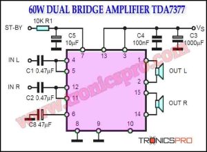
![60W Double-Bridge Stereo Amplifier using TDA7377]()
60W Double-Bridge Stereo Amplifier using TDA7377
![Stereo Amplifier TDA7297 Dual-Bridge Circuit Diagram]()
Stereo Amplifier TDA7297 Dual-Bridge Circuit
![300W Audio Power Amplifier Circuit Diagram]()
300W Audio Power Amplifier Circuit Diagram using 2N3055 & MJ2955
![TDA7240A Bridge Amplifier 20W Circuit Diagram]()
TDA7240A Bridge Amplifier 20W Circuit Diagram
![Simple Inverter using Symmetrical Multivibrator Circuit Diagram]()
Simple Inverter Circuit Diagram with Multivibrator
![1000W Amplifier Circuit Diagram based 2SC5200 & 2SA1943]()
1000W Amplifier Circuit Diagram based 2SC5200 & 2SA1943 | Bell Power