Introduction
The C9013 transistor is an NPN small signal transistor commonly used for low-power amplification and switching applications. It belongs to the well-known C901x series, which is highly popular in consumer electronics, radio frequency circuits, and general-purpose low-voltage amplifier designs. With a maximum collector current of 500 mA and a collector-emitter voltage (Vceo) up to 50V, the C9013 offers a good balance between performance and reliability in compact circuit layouts.

Engineers and hobbyists frequently use the C9013 NPN transistor in audio preamplifiers, signal processing circuits, oscillators, and low-power driver stages due to its moderate current gain (hFE 40–400) and transition frequency around 100 MHz. Its low saturation voltage and fast switching speed make it efficient for digital and analog signal switching.
C9013 NPN Small Signal Transistor

The transistor is typically packaged in a TO-92 plastic package, which ensures thermal stability and easy installation on PCB layouts. Its low cost, wide availability, and proven reliability make the C9013 transistor a versatile choice in various DIY electronics projects, consumer devices, and industrial control circuits.
C9013 Pinout

Pin Configuration
| Pin# | Pin Name | Pin Description |
|---|---|---|
| 1 | Emitter (E) | Current flows out through this terminal. |
| 2 | Base (B) | Controls the transistor’s biasing and switching operation. |
| 3 | Collector (C) | Current flows in through this terminal when the transistor is ON. |
Key Features
- NPN Silicon Small Signal Transistor
- High transition frequency suitable for RF and audio circuits
- Moderate collector current handling up to 500 mA
- Low collector-emitter saturation voltage for efficient switching
- Reliable in low-power amplification and general-purpose designs
- Easy PCB mounting with standard TO-92 package
Characteristics
- Transistor Type: NPN
- Package Type: TO-92
- Collector-Emitter Voltage (Vceo): 50V
- Collector-Base Voltage (Vcbo): 60V
- Emitter-Base Voltage (Vebo): 5V
- Collector Current (Ic): 500 mA
- DC Current Gain (hFE): 40 to 400
- Transition Frequency (fT): 100 MHz (typical)
- Power Dissipation (Ptot): 625 mW
- Junction Temperature (Tj max): 150°C
Comparison : 9013, 2SC9013, S9013, KTN9013
The 9013, 2SC9013, S9013, and KTN9013 all belong to the same transistor family, sharing identical electrical parameters and characteristics. The distinction lies mainly in naming conventions and manufacturers. The 2SC9013 follows the Japanese Industrial Standard (JIS) naming scheme, where “2S” indicates a silicon transistor and “C” represents an NPN device. The S9013 label is a shorter form often used by Chinese and Taiwanese manufacturers for compact marking on TO-92 cases. The KTN9013, produced by Korea Electronics (KEC), maintains the same performance but ensures consistent quality and manufacturing standards.
In practical use, all four versions 9013, 2SC9013, S9013, and KTN9013 are fully interchangeable in most circuits, offering reliable performance in small-signal amplification, switching, and low-power RF applications.
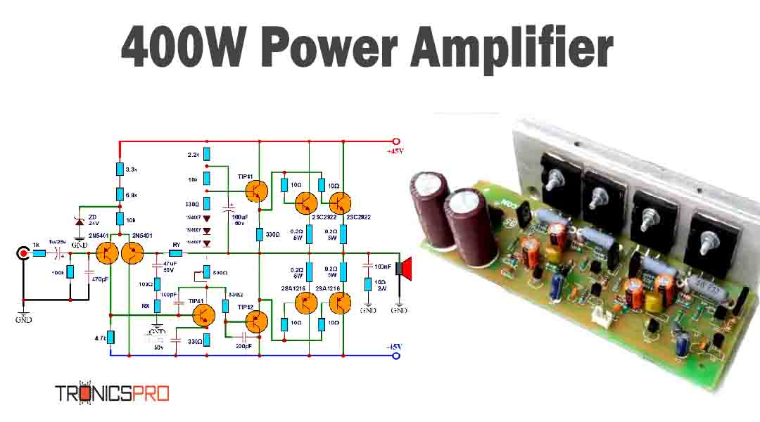
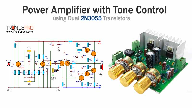
More Circuit Layouts



Key Applications of C9013 Transistor
- Low-power audio amplifiers
- Signal processing and preamplifier circuits
- Oscillator and driver circuits
- Switching applications in digital electronics
- Voltage and current sensing circuits
- DIY and educational electronic projects
PNP Complementary Transistor
- The PNP complementary transistor of C9013 is the C9012. Both share similar characteristics but operate with opposite polarities, making them ideal for use together in push-pull amplifier configurations and complementary driver stages.
Equivalent of C9013 NPN Small Signal Transistor
- 2N2222
- BC337
- 2SC945
- 2SC828
- S8050
- MPS2222A
- KTC9013 (equivalent Korean variant)
(Pin configuration of some transistors mentioned above may different from C9013).
Datasheet of C9013 NPN Small Signal Transistor
Click the following Button to download the datasheet of C9013 Transistor :
More projects, You may like:
- Video Transmitter DIY Homemade FM Radio Transmitter
- Adjustable Power Supply DIY Battery Charger
- 12V-220V 500 Watt inverter DIY Homemade
- MPPT Solar Charge Controller DIY Homemade
- DIY LA4440 bass amplifier homemade
For more project and circuit diagrams, you can go through the Schematics in the main menu where you can find many interesting projects and circuit diagrams like audio amplifier circuits, voltage booster circuit, battery charger circuit and timer circuits etc., which are all beginner circuit projects. Feel free to check them out!

Thank you for visiting th


