Introduction
The BD537 is a silicon NPN epitaxial-base power transistor designed for medium-power switching and linear amplifier applications. It is known for its robust performance, high collector current capability, and good gain stability across a wide operating temperature range. The BD537 is widely used in audio amplifiers, voltage regulators, and driver circuits, offering excellent reliability for both industrial and consumer electronics.
This transistor belongs to the BD series of power devices, featuring a durable TO-220 plastic package for efficient heat dissipation. Its strong current handling capacity and moderate voltage rating make it suitable for applications where a balance between power and thermal management is critical. The BD537’s low saturation voltage and good DC gain contribute to its effectiveness in amplifier output stages and power control circuits.
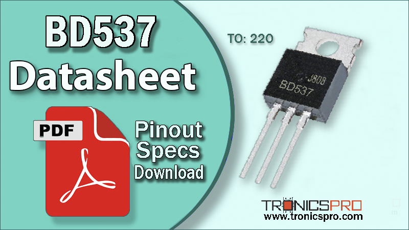
BD537 NPN Transistor
As an NPN transistor, the BD537 sources current when driven by a positive base signal. It works efficiently when paired with its PNP complementary device BD538, allowing it to be used in push-pull configurations for high-fidelity audio or symmetrical switching applications. This complementary pairing ensures balanced waveform handling and minimized distortion.
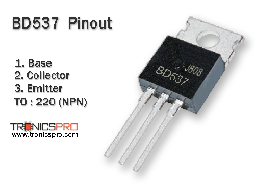
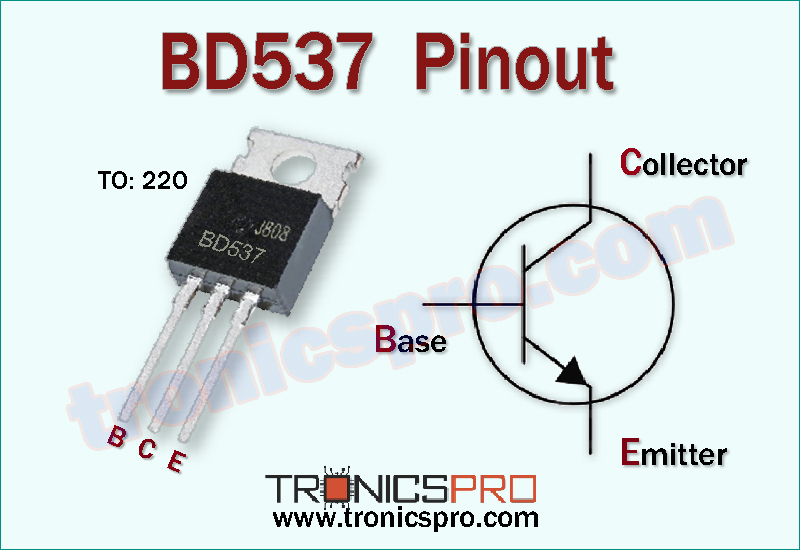
Pinout of BD537
Key Features
- High collector current capability
- Medium voltage rating for versatile power circuits
- Low collector-emitter saturation voltage
- High DC current gain and thermal stability
- Reliable TO-220 package with efficient heat dissipation
- Suitable for switching and linear amplifier use
- Complementary to BD538 PNP transistor
Specifications/Characteristics
- Collector-Base Breakdown Voltage (VCBO) = 80 V
- Collector-Emitter Breakdown Voltage (VCEO) = 80 V
- Emitter-Base Breakdown Voltage (VEBO) = 5 V
- Collector Current (IC) = 8 A
- Total Power Dissipation (Ptot) at TC = 25 °C = 50 W
- Junction Temperature (TJ) = 150 °C
- Storage Temperature Range (Tstg) = –65 °C to +150 °C
- DC Current Gain (hFE) = 40 (typical at IC = 4 A, VCE = 4 V)
- Collector-Emitter Saturation Voltage (VCE(sat)) = 0.8 V (IC = 4 A, IB = 0.4 A)
- Transition Frequency (fT) = 3 MHz
Pin Configuration
| Pin# | Pin Name | Pin Description |
|---|---|---|
| 1 | Base | Input control terminal |
| 2 | Collector | Output terminal to load |
| 3 | Emitter | Return terminal / ground path |
Comparison BD537 (NPN) vs BD538 (PNP)
- The BD537 is an NPN transistor, while the BD538 is its PNP complement. Both share identical voltage and current characteristics, designed to operate together in complementary or push-pull configurations. The BD537 handles the positive half-cycle of the waveform, while the BD538 manages the negative half, ensuring balanced and distortion-free performance in amplifier designs.
- When paired, they provide symmetrical operation, stable gain, and efficient thermal performance, making them ideal for audio power amplifiers, driver circuits, and controlled power stages.
More Circuit Layouts


Key Applications of BD537 NPN Transistor
- Audio amplifier output stages
- Power control and regulation circuits
- Switching regulators and driver modules
- Complementary push-pull amplifier circuits
- Industrial automation systems
- General-purpose medium-power amplification
PNP Complimentary Transistor
- The PNP complementary transistor for BD537 is BD538.
Equivalent Transistors of BD537 NPN Transistor
- Equivalent or replacement transistors include BD535, BD441, and TIP41C, depending on circuit voltage and current requirements.
- Ensure electrical parameters meet or exceed the BD537 ratings before substitution.
(Pin configuration of some transistors mentioned here may different from BD537).
Datasheet of BD537 NPN Transistor
Click the following Button to download the datasheet of BD537 Transistor :
More projects, You may like:
- Video Transmitter DIY Homemade FM Radio Transmitter
- Adjustable Power Supply DIY Battery Charger
- 12V-220V 500 Watt inverter DIY Homemade
- MPPT Solar Charge Controller DIY Homemade
- DIY LA4440 bass amplifier homemade
For more project and circuit diagrams, you can go through the Schematics in the main menu where you can find many interesting projects and circuit diagrams like audio amplifier circuits, voltage booster circuit, battery charger circuit and timer circuits etc., which are all beginner circuit projects. Feel free to check them out!
Thank you for visiting the article.