Introduction
An Attenuator Limiter (circuit) is an essential tool for anyone who records music. It helps to regulate the level of incoming signals. Making sure that no signal exceeds a pre-set limit and protect your recording equipment from damage. This can be especially useful in live sound environments. Allowing you to keep it sounding clear and distortion-free without overloading the speakers or amplifiers. In addition to preventing damage and preserving sound quality, Attenuator Limiters can also help make it more efficient. Use of headroom by ensuring that only the desired frequencies stay above the threshold. Ultimately, this makes getting that perfect sound much easier!
Circuit Diagram
of Attenuator Limiter Circuit Diagram

More Circuit Layouts


Working Explanation
of Attenuator Limiter Circuit Diagram
The attenuator/limiter may be of interest to readers involved in producing soundtracks with (small-format) films (home movies, perhaps), or producing sound samples using ‘performers’ (including animals) whose dynamic range is too large.
The signal arrives on the input terminals for processing shown on the left-hand side of the attenuator limiter circuit diagram. Potentiometer P1‚ allows the input signal to be adjusted before it reaches the input of IC1‚on MC3340P from Motorola. The level adjustment is necessary to prevent sudden variations in the input signal level from reaching the output of the circuit. The MC3340P offers an attenuation range of up to 80 dB for frequencies up to 1 MHz. The distortion introduced by it is smaller than 1% if the attenuation does not exceed 15 dB or 3% for an attenuation of 40 dB.
More Explanations…
The value of the RC networks at the input and the output is such that the lower cut-off frequency of the overall circuit does not exceed 12 Hz. Resistor Rg defines the time constant of the rectifier formed by diodes D1‚and D2. Its value prevents the distortion from increasing when the input signal frequency decreases. The current supplied by the MC3340 via pin 2 produces a voltage across Rg, which, without the action of buffer op-amp IC3, would cause excessive attenuation. The two op amps in ICâ‚‚ form a kind of level adaptor that makes the conditioned signal available at the output terminals.
The circuit draws a current of about +18 mA and -4 mA. If it is decided to give it a dedicated power supply, a ‘standard’ design is based on two integrated voltage regulators. Powered by a bridge rectifier, smoothing and filtering capacitors, and a mains transformer with a center tap will do nicely.
The circuit has a small additional advantage: it helps to reduce the audio level of commercials and advertising on radio and TV. Which are often broadcast at a higher sound level than the programs they rudely interrupt. This attenuator circuit makes them fall into line again.
You may also like:
 Multi Color Led Circuit Diagram
- 500W Power Amplifier Circuit using c5200 a1943
- 400W Amplifier Circuit Diagram using 2SC2922 & 2SA1216
- 120W MOSFET Amplifier Circuit Diagram using IRFP240 & IRFP9240
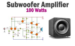
- 100W Subwoofer Amplifier Circuit Diagram
- 400W Stereo Amplifier Circuit using STK4050
- Bass Booster Circuit Diagram using Single Transistor 2N2222
- 50W Amplifier Circuit Diagram using STK4036