The IRF830 is a high-voltage N-Channel MOSFET commonly used in power switching and high-efficiency conversion stages. It is designed to operate reliably in circuits that require stable switching performance at elevated voltages. The IRF830 pinout follows the standard TO-220 arrangement, making it easy to integrate into existing power supply, SMPS, and inverter designs.

Introduction to IRF830 N-Channel MOSFET
The IRF830 offers excellent switching behavior due to its MOSFET structure, enabling reduced conduction losses and improved power efficiency. Its ability to handle high voltages makes it suitable for offline converters, high-voltage drivers, and power regulation stages. The device’s fast switching capability supports high-frequency applications, leading to compact and efficient circuit designs.
Built with a rugged silicon process, the IRF830 provides consistent thermal performance, enhanced electrical stability, and high reliability. It is commonly used in power supplies, motor control circuits, high-voltage converters, LED drivers, and various high-speed switching topologies where durability and performance are critical.
IRF830 N-Channel MOSFET

Pinout of IRF830

Pin Configuration of IRF830 Pinout
The IRF830 pinout in the TO-220 package is ordered Gate – Drain – Source (G–D–S) when viewing the front (leads downward). The metal tab is typically connected to the drain, which also helps thermal dissipation when mounted to a heatsink.
| Pin# | Pin Name |
|---|---|
| 1 | Gate |
| 2 | Drain |
| 3 | Source |
Correct pin identification is essential in high-voltage circuits to avoid reverse connections that can damage the MOSFET or upstream circuitry.
Key Features of IRF830 MOSFET
- High-voltage switching capability
- Fast and efficient switching performance
- Rugged and thermally stable construction
- Suitable for high-frequency power applications
- Low gate drive requirement
- Reliable performance for industrial-grade circuits
- Standard TO-220 package for easy mounting
Datasheet and Specifications of IRF830 MOSFET
- VDS (Drain-Source Voltage): 500V
- VGS (Gate-Source Voltage): ±20V
- ID (Continuous Drain Current): 4.5A
- IDM (Pulsed Drain Current): 18A
- RDS(on) (Drain-Source On-Resistance): 1.5Ω
- Ptot (Total Power Dissipation): 100W
- Tstg (Storage Temperature Range): -65°C to +150°C
- TJ (Junction Temperature): 150°C
- Package Type: TO-220
- Pin Configuration: G-D-S
Working Principle of IRF830 MOSFET
The IRF830 is a voltage-controlled device: applying a positive VGS above threshold forms an n-type channel between drain and source, allowing current to flow. In switching mode it transitions between cutoff and saturation/ohmic regions, controlled by gate voltage and switching edge timing, enabling efficient PWM operation in power converters. In linear (analog) operation it can be biased to act as a variable resistor for amplification or regulation, though care must be taken with thermal dissipation when operated in the linear region at high voltages.
More Circuit Layouts


Applications of IRF830 MOSFET
- Offline SMPS primary switches (flyback/forward topologies)
- High-voltage DC-DC converters and regulators
- Induction heating and high-voltage power stages
- High-voltage motor controllers and drivers (medium current)
- Lamp ballasts, LED drivers (high-voltage designs)
- Laboratory and test equipment requiring rugged high-voltage switching
Equivalent and Alternative MOSFETs
When replacing an IRF830, ensure comparable VDS, ID, RDS(on) and SOA:
- IRF830A (vendor variants)
- IXFHxx series with similar VDS (verify RDS and SOA)
- MTP series high-voltage MOSFETs (check pinouts)
- IRFP series devices for higher current (may require different drive and heatsinking)
Always cross-check RDS(on), VDS, IDM, package pinout and thermal limits before substituting.
Frequently Asked Questions (FAQ)
Q1: What is the IRF830 pinout?
TO-220 front view (leads down): Gate – Drain – Source (G–D–S). The tab is usually the drain.
Q2: Is IRF830 suitable for 100 kHz switching?
It can be used at moderate switching frequencies, but switching losses and gate charge must be assessed, for high-frequency SMPS consider MOSFETs optimized for low gate charge and lower RDS(on).
Q3: Do I need a heatsink for IRF830?
Yes — for continuous or high-power operation a properly sized heatsink (and thermal interface) is required to stay within TJ limits.
Q4: Can IRF830 be driven directly from logic levels?
No — the IRF830 requires a proper gate drive (often ~10–12 V) for low conduction losses; microcontroller GPIO pins are insufficient without a driver stage.
Conclusion
The IRF830 is a proven high-voltage N-channel MOSFET suitable for medium-power, high-voltage switching applications where 500 V blocking, acceptable switching speed, and TO-220 thermal performance are required. Proper attention to IRF830 pinout, gate-drive voltage, and thermal management will ensure reliable operation in SMPS, inverter, and other high-voltage power systems.
Datasheet & Pinout of IRF830 N-Channel MOSFET
Click the following Button to download the datasheet of IRF830 MOSFET :
More projects:
- Video Transmitter DIY Homemade FM Radio Transmitter
- Adjustable Power Supply DIY Battery Charger
- 12V-220V 500 Watt inverter DIY Homemade
- MPPT Solar Charge Controller DIY Homemade
- DIY LA4440 bass amplifier homemade
For more project and circuit diagrams, you can go through the Schematics in the main menu where you can find many interesting projects and circuit diagrams like audio amplifier circuits, voltage booster circuit, battery charger circuit and timer circuits etc., which are all beginner circuit projects. Feel free to check them out!
Thank you for visiting the article.
You may also like:
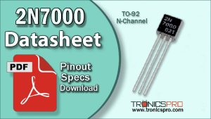
![2n7000 datasheet pinout equivalent specification]()
2N7000 Pinout, Equivalent, Application, Datasheet
![IRF820 datasheet pinout equivalent specification application mosfet n-channel]()
IRF820 Pinout, Equivalent, Application, Datasheet
![IRF9510 datasheet pinout equivalent specification mosfet]()
IRF9510 Pinout, Equivalent Application, Datasheet
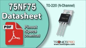
![75NF75 datasheet pinout equivalent specification application mosfet n-channel]()
75NF75 Pinout, Equivalent, Application, Datasheet
![IRF1010 datasheet pinout equivalent specification application mosfet n-channel]()
IRF1010 Pinout, Equivalent, Application, Datasheet
![IRF530 MOSFET Datasheet Pinout]()
IRF530 Power MOSFET N-Channel Datasheet
![irf9530 datasheet pinout equivalent specification mosfet]()
IRF9530 Pinout, Equivalent Application, Datasheet
![FQP22N30 datasheet pinout equivalent specification application mosfet n-channel]()
FQP22N30 Pinout Equivalent Application Datasheet