The IRF520 is a widely used N-Channel power MOSFET designed for medium-power switching, PWM motor control, audio circuits, and general power management applications. This device delivers excellent efficiency, fast switching, and reliable operation in power supplies and driver circuits. The IRF520 pinout is an important detail for hobbyists and engineers because correct terminal identification ensures stable and safe circuit performance.

Introduction to IRF520 N-Channel MOSFET
The IRF520 is an enhancement-mode N-Channel MOSFET commonly used in DC motor drivers, switching regulators, battery chargers, high-speed switching applications, and audio amplifier stages. Operating at up to 100V drain-source voltage and 7A continuous current, it is ideal for medium-power loads. Its TO-220 package allows proper heat dissipation, making it a strong choice in educational electronics and industrial circuits.
IRF520 N-Channel MOSFET

Pinout of IRF520

Pin Configuration of IRF520 Pinout
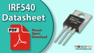
The IRF520 comes in a TO-220 package with the following pin configuration (front view, pins downward):
| Pin# | Pin Name |
|---|---|
| 1 | Gate |
| 2 | Drain |
| 3 | Source |
This simple G-D-S pin structure allows easy interfacing with microcontrollers, driver ICs, and discrete circuits.
Key Features of IRF520 MOSFET
- Fast switching response
- Low gate drive requirement
- High drain-source voltage capability
- Suitable for PWM and switching applications
- Robust TO-220 package for improved thermal handling
- Ideal for medium-power DC loads
- Reliable performance in high-efficiency circuits
IRF520 MOSFET Datasheet and Specifications
- Drain-Source Voltage (VDS): 100V
- Gate-Source Voltage (VGS): ±20V
- Continuous Drain Current (ID): 7A
- Pulsed Drain Current (IDM): 40A
- Total Power Dissipation (Ptot): 35W
- On-Resistance (RDS(on)): 0.27Ω
- Junction Temperature (TJ): 65°C to +175°C
- Package Type: TO-220
- Pin Configuration: G-D-S
Working Principle of IRF520 MOSFET
The IRF520 operates as an enhancement-mode MOSFET, meaning it stays OFF until a positive voltage is applied to the gate terminal. When the gate voltage exceeds the device’s threshold, it allows current to flow from the drain to the source. Its high VDS rating and low RDS(on) allow efficient switching, making it suitable for motor control, LED dimming, and power switching with minimal losses.
More Circuit Layouts


Applications of IRF520 MOSFET
- Motor drivers and DC speed controllers
- SMPS and power converters
- Relay replacement in digital circuits
- LED dimmers and PWM controllers
- High-frequency switching circuits
- Battery-operated power stages
- Audio and RF experimental circuits
Equivalent and Alternative MOSFETs
Possible equivalents or alternatives include:
- IRF530
- IRF540
- IRFZ44N
- IRLZ44N (logic-level alternative)
- STP55NF06
- IRF3205 (higher current alternative)
Always verify voltage and current ratings before substitution.
Frequently Asked Questions (FAQ)
Q1: Is the IRF520 a logic-level MOSFET?
No. It requires a higher gate voltage (typically 10V) for full switching.
Q2: Can I drive IRF520 with Arduino or Raspberry Pi?
Not directly. A MOSFET driver or transistor driver stage is recommended.
Q3: What type of loads can IRF520 control?
Motors, LEDs, solenoids, and other DC loads up to 7A.
Q4: Does IRF520 need a heatsink?
Yes, for loads above 1–2A continuous, a heatsink is recommended.
Conclusion
The IRF520 N-Channel MOSFET is a versatile and efficient medium-power switching device suitable for countless electronics projects and industrial applications. Its excellent performance, easy pinout structure, and robust TO-220 package make it a dependable choice for motor drivers, PWM circuits, and power management systems. With good efficiency and thermal stability, the IRF520 remains one of the most widely used MOSFETs in educational and embedded electronics.
Datasheet & Pinout of IRF520 N-Channel MOSFET
Click the following Button to download the datasheet of IRF520 MOSFET :
More projects:
- Video Transmitter DIY Homemade FM Radio Transmitter
- Adjustable Power Supply DIY Battery Charger
- 12V-220V 500 Watt inverter DIY Homemade
- MPPT Solar Charge Controller DIY Homemade
- DIY LA4440 bass amplifier homemade
For more project and circuit diagrams, you can go through the Schematics in the main menu where you can find many interesting projects and circuit diagrams like audio amplifier circuits, voltage booster circuit, battery charger circuit and timer circuits etc., which are all beginner circuit projects. Feel free to check them out!

Thank you for visiting the article.


