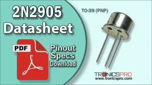
The 2N4427 is a high-frequency NPN silicon transistor designed for RF amplification, signal transmission, and VHF oscillator circuits. It comes in a TO-39 metal can package, ensuring excellent thermal performance and shielding from electromagnetic interference. The 2N4427 pinout follows the Emitter–Base–Collector (E-B-C) configuration, making it easy to integrate into standard RF amplifier layouts and communication equipment.
Capable of handling up to 0.5 A collector current, with a collector-emitter voltage of 20 V and collector-base voltage of 40 V, the 2N4427 delivers 3.5 W of total power dissipation. This makes it ideal for VHF transmitters, RF drivers, signal boosters, and radio communication amplifiers up to 175 MHz.

Introduction to 2N4427 NPN Transistor
The 2N4427 is a broadband NPN RF transistor widely used in VHF and low-UHF transmitters, oscillators, and signal amplifiers. Constructed with planar epitaxial silicon technology, it provides high gain, low noise, and excellent linearity across high-frequency ranges.
Its TO-39 metallic package not only ensures effective heat dissipation but also enhances shielding against RF noise. These properties make the 2N4427 an excellent choice for RF driver stages in two-way radios, signal processing, and communication transmitters.
2N4427 NPN Transistor

Pinout of 2N4427

Pin Configuration of 2N4427 Pinout
| Pin# | Pin Name |
|---|---|
| 1 | Emitter |
| 2 | Base |
| 3 | Collector |
Key Features of 2N4427 Transistor
- NPN silicon RF transistor
- Designed for high-frequency and VHF applications
- High linear gain and low distortion
- Metal TO-39 package for superior heat dissipation
- Operates efficiently up to 175 MHz
- Ideal for signal amplification and transmission stages
2N4427 Transistor Datasheet and Specifications
- Transistor Type: NPN Silicon
- Collector-Emitter Voltage (Vce): 20 V
- Collector-Base Voltage (Vcb): 40 V
- Emitter-Base Voltage (Veb): 4 V (typical)
- Collector Current (Ic): 0.5 A
- Total Power Dissipation (Ptot): 3.5 W
- DC Current Gain (hFE): 20 – 120
- Transition Frequency (fT): 175 MHz
- Package Type: TO-39 Metal Can
- Pin Configuration: Emitter – Base – Collector (E-B-C)
Equivalent and Alternative Transistors
The following transistors can serve as 2N4427 equivalents depending on circuit design and frequency range:
- 2N3866 – NPN, 28 V, 5 W RF transistor
- MRF237 – NPN, high-frequency driver transistor
- BFR96 – NPN, low-power RF amplifier
- 2N5109 – NPN, broadband amplifier transistor
Always verify pin orientation and frequency response before substitution.
More Circuit Layouts


Applications of 2N4427 Transistor
The 2N4427 is specifically engineered for high-frequency electronic circuits, offering reliable gain and stable performance:
- RF driver and power amplifier stages
- VHF oscillator and frequency generator circuits
- Radio and communication transmitters
- Signal booster and pre-amplifier modules
- Test and measurement RF equipment
- Antenna signal amplifiers
Working Principle of 2N4427 Transistor
As an NPN bipolar junction transistor, the 2N4427 becomes active when the base receives a small positive current relative to the emitter, allowing a much larger current to flow from collector to emitter. In RF circuits, this controlled current flow amplifies weak input signals at high frequencies while maintaining linearity and stability.
Advantages of 2N4427 Transistor
- Excellent high-frequency performance
- Low noise figure for clean signal amplification
- Robust TO-39 metal enclosure
- Reliable at elevated temperatures
- Stable operation in analog and RF conditions
Conclusion
The 2N4427 NPN transistor is a high-frequency silicon device designed for RF amplification and VHF oscillator circuits. With its 20 V / 40 V ratings, 0.5 A current capacity, and 3.5 W dissipation, it provides consistent and efficient performance for radio frequency amplifiers and signal transmitter designs. Its E-B-C TO-39 package offers durability and minimal noise interference, making it a top choice among RF engineers and hobbyists alike.
Datasheet & Pinout of 2N4427 NPN Transistor
Click the following Button to download the datasheet of 2N4427 Transistor :
More projects, You may like:
- Video Transmitter DIY Homemade FM Radio Transmitter
- Adjustable Power Supply DIY Battery Charger
- 12V-220V 500 Watt inverter DIY Homemade
- MPPT Solar Charge Controller DIY Homemade
- DIY LA4440 bass amplifier homemade
For more project and circuit diagrams, you can go through the Schematics in the main menu where you can find many interesting projects and circuit diagrams like audio amplifier circuits, voltage booster circuit, battery charger circuit and timer circuits etc., which are all beginner circuit projects. Feel free to check them out!

Thank you for visiting the article.


