Tag: power supply circuit diagram

LM2574 Switch-Mode Power Supply Circuit

LM2574 Switch-Mode Power Supply Circuit Diagram

The use of the LM2574 in designing a Switch-Mode Power Supply that is tailored for high efficiency and precision regulation. The LM2574 is a switching regulator IC that converts an input voltage to a regulated output voltage using pulse-width modulation (PWM) techniques. It operates in the range between 4.5V to 40V of input voltage and can provide a maximum output current of 500mA. It comes in a TO-220 or TO-263 package and is easy to integrate into circuit design.

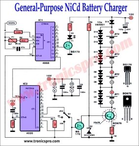
General-Purpose NiCd Battery Charger Circuit

General-Purpose NiCd Battery Charger Circuit Diagram

A general-purpose NiCd battery charger is an essential device for anyone who uses electronic devices that require nickel-cadmium batteries. It ensures that the battery is charged safely and efficiently, which can help to extend the lifespan of the battery and maximize the performance of the device. With a NiCd battery charger, users can confidently use their electronic devices without worrying about battery life or performance issues.

20 Watt Power Amplifier Circuit Diagram

The amplifier using two SE9301 & SE9401 push-pull Darlington TO-220 transistors, one 2N5961 transistor, and 8 ohms speakers is an excellent choice for anyone looking to amplify the sound of their music and create powerful, clear sound without consuming too much energy. It is, therefore, the ideal choice for music lovers looking to create a powerful and efficient audio setup.

15W Power Amplifier Circuit Diagram

The circuit diagram of a 15-watt low-distortion power amplifier using NSP5194 PNP and NSP5191 NPN transistors in the output stage, LM378 IC in the pre-amplifier, and a 13-volt power supply provides a clean, high-quality audio signal output. The circuit design relies on the complementary symmetry amplifier configuration of the PNP and NPN transistors in the output stage, as well as the use of a feedback loop for low distortion.

Automatic PWM Battery Charger 12V-24V

In this video I have made an automatic PWM battery using Arduino, this battery charger can charge 12V or 24V battery, it can automatically detect battery voltage and set charging parameters according to battery and start charging the battery, the system also has leds to display battery level. I hope you will enjoy this video Gerber files and circuit diagram is given below.

12V Battery Charger Homemade

In this video I have made a 12V Battery Charger Homemade with a feature to indicate when battery is fully charged. I have tried to make this video as easy as it could be and used common components. Portable chargers are great for on-the-go charging, allowing you to keep your devices powered up while you’re away from home.

12V Battery Charger Auto-cut-off Homemade

In this video I have made a 12V Battery Charger Auto-cut-off. It can charge batteries up to 60Ah. I have made this charger auto cutoff using very simple component. I hope this video will be helpful to you. To get started, you’ll need a transformer with a voltage rating between 12-15 volts, as well as some diodes and capacitors to create the rectifier circuit.

Next Page » « Previous Page