Introduction
A subwoofer is an essential component for any audio enthusiast looking to enrich their listening experience with deep and powerful bass. A subwoofer amplifier circuit low pass is crucial in driving the subwoofer, and the TDA2050 IC offers an excellent solution for beginners due to its simplicity and reliability. In this article, we will explore the circuit diagram and specifications of the TDA2050 IC, as well as discuss its low pass filter functionality.
TDA2050 IC Specifications:
The TDA2050 is a monolithic integrated circuit specifically designed for audio amplification applications. It is a class AB amplifier capable of delivering up to 32W RMS of power. The IC operates with a wide supply voltage range of ±4.5V to ±25V, making it suitable for various audio systems. It features high output current and exceptional thermal stability, ensuring optimal performance and protection against overheating.
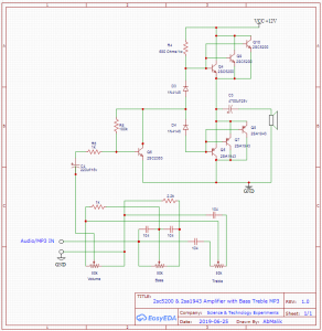
Subwoofer Amplifier Circuit Diagram Low Pass
This project can be built using a few basic components. The circuit diagram of this project is shown below.


More Circuit Layouts


Components List of Subwoofer Amplifier Circuit Low Pass
Following is the list of all components used in this project:
TDA2050 IC x 1
C2655 Transistor x 1
C2383 Transistor x 1
3.3k Resister x 1
22Ω Resister x 2
100Ω Resister x 2
2.2k Resister x 1
22k Resister x 2
680Ω Resister x 1
2.2Ω Resister x 1
10uF Capacitor x 2
100uF Capacitor x 1
47uF Capacitor x 1
220uF Capacitor x 3
1uF Capacitor x 2
22uF Capacitor x 1
100nF Capacitor x 2
0.47uF Capacitor x 1
22k Potentiometer x 1
+/-12V Power Supply
Explanation of Subwoofer Amplifier Circuit Low Pass
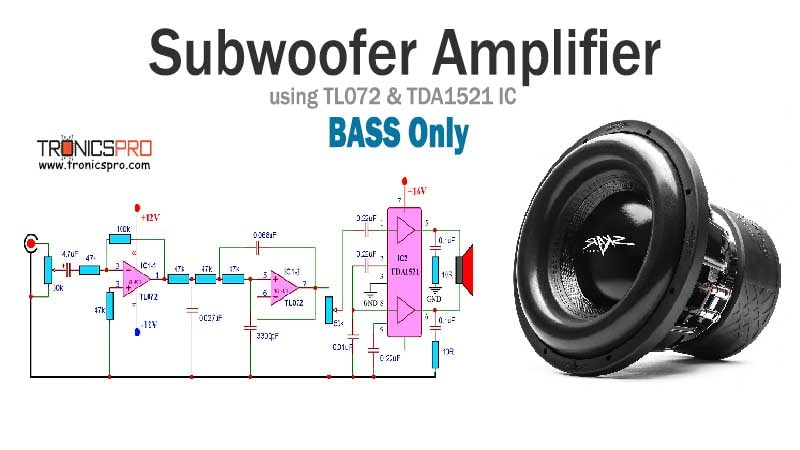
The subwoofer amplifier circuit using the TDA2050 IC is relatively straightforward, making it perfect for beginners. The low pass filter using C2655 and C2383 transistors, connected to pin 1 of the IC, allows only low-frequency signals to pass through, ensuring that only bass sounds are sent to the subwoofer. This eliminates any unwanted high-frequency noise or distortion from reaching the subwoofer, resulting in cleaner and more accurate bass reproduction.
The TDA2050 IC requires a few external components to function correctly. A few key components are as follows:
- Capacitors: Capacitors are used to couple and filter audio signals, ensuring a clean and stable output. Various capacitors are used in different stages of the circuit, such as input capacitors, coupling capacitors, and feedback capacitors.
- Resistors: Resistors help control the gain and biasing of the amplifier circuit. They provide stability and prevent excessive current flow.
- Inductors: Inductors, in combination with capacitors, can form resonant circuits to further filter and shape the audio signals.
Conclusion
The TDA2050 IC provides an excellent solution for beginners looking to build a subwoofer amplifier circuit with low pass filter. Its specifications, including high output power, wide supply voltage range, and thermal stability, make it highly versatile for various audio applications. By incorporating the low pass filter functionality through external components, unwanted frequencies can be removed, ensuring that only clean and powerful bass signals reach the connected subwoofer.
The TDA2050 IC, combined with the subwoofer amplifier circuit, presents an opportunity for audio enthusiasts to create an immersive audio experience at an affordable cost. The simplicity of the circuit, along with the reliable performance of the IC, makes it an ideal choice for beginners venturing into DIY audio projects.
More projects, You may like:
- Video Transmitter DIY Homemade FM Radio Transmitter
- Adjustable Power Supply DIY Battery Charger
- 12V-220V 500 Watt inverter DIY Homemade
- MPPT Solar Charge Controller DIY Homemade
- DIY LA4440 bass amplifier homemade
For more project and circuit diagrams, you can go through the Schematics in the main menu where you can find many interesting projects and circuit diagrams like audio amplifier circuits, voltage booster circuit, and timer circuits. Feel free to check them out!

Thank you for visiting the article.
You may also like:
![300W Power Amplifier Circuit DIY Homemade]()
300W Power Amplifier Circuit Diagram DIY Homemade
![High-Level 4-Channel Audio Mixer Circuit Diagram]()
High-Level 4-Channel Audio Mixer Circuit Diagram
![Stepper Motor Control Circuit Diagram]()
Stepper Motor Control Circuit Diagram
![2sc5200 2sa1943 amplifier circuit diagram]()
C5200 A1943 amplifier circuit diagrams
![Low Pass Filter Circuit Subwoofer using TL072 IC]()
Subwoofer Filter Circuit using TL072 for Low Pass
![TDA2030 Stereo Amplifier Circuit Diagram]()
TDA2030 Stereo Amplifier Circuit Diagram
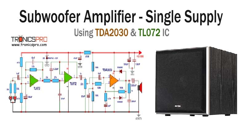
![Subwoofer Amplifier Circuit Diagram using TDA2030 & JRC4558 IC Thumbnail]()
Subwoofer Amplifier Circuit Diagram using TDA2030 & JRC4558 IC
![200W HiFi power Amplifier Circuit Diagram using Sanken 2SC2922 2SA1216]()
200W HiFi Power Amplifier Circuit Diagram using Sanken Transistors